
DISPLAY BOARD FOR RADAR GUN
The described circuit is designed to process Doppler radar signals effectively. It begins by receiving the raw Doppler signal, which is typically a low-level analog signal. The first stage of the circuit involves amplification, where the weak radar signal is boosted to a more manageable level. This amplification is critical for ensuring that the subsequent processing stages can accurately interpret the signal.
Following the amplification, the signal undergoes a limiting stage. This is essential for eliminating noise and preventing signal distortion, which can occur due to fluctuations in the input signal. By limiting the signal, the circuit ensures that only the relevant frequency components are passed on to the next stage.
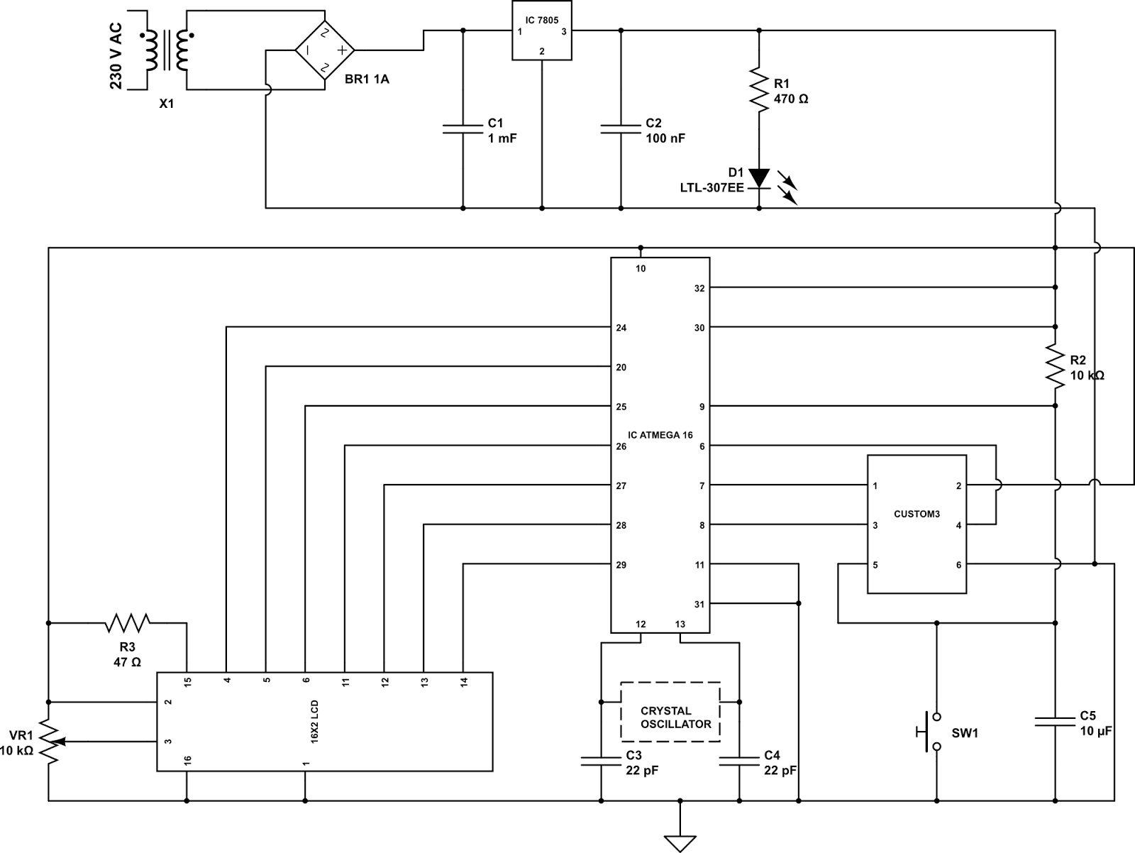
The processed frequency is then directed to a counter (U4), which counts the number of cycles of the incoming signal over a specified time period. This frequency information is crucial for calculating the speed of an object based on the Doppler effect. The counter's output is subsequently fed into a display circuit composed of components DISP1, DISP2, U5, and U6. This display circuit provides a visual representation of the speed measurement, allowing users to easily read the results.
Calibration of the counter is handled by the clock circuit (U2B), which generates a precise timing reference for the counting operation. Resistors R21 and R22 play a pivotal role in this calibration process. By adjusting R21, users can modify the scaling of the readout, enabling the display to show speed in kilometers per hour or other desired units. This flexibility in calibration ensures that the circuit can be tailored to meet specific application requirements.
Overall, this circuit exemplifies a robust design for radar signal processing, featuring amplification, limiting, counting, and display capabilities, all of which are essential for accurate speed measurements in various applications.This circuit takes signal (doppler) from a radar,un, amplifies and limits it, and feeds the frequency into a counter (U4) and display circuit (DISP1, DISP2,U5,U6). Counter calibration is set by clock circuit U2B. Calibration is obtained via R21 and R22. R21 can be changed if kilometers/hour readout is desired.. 🔗 External reference
Related Circuits
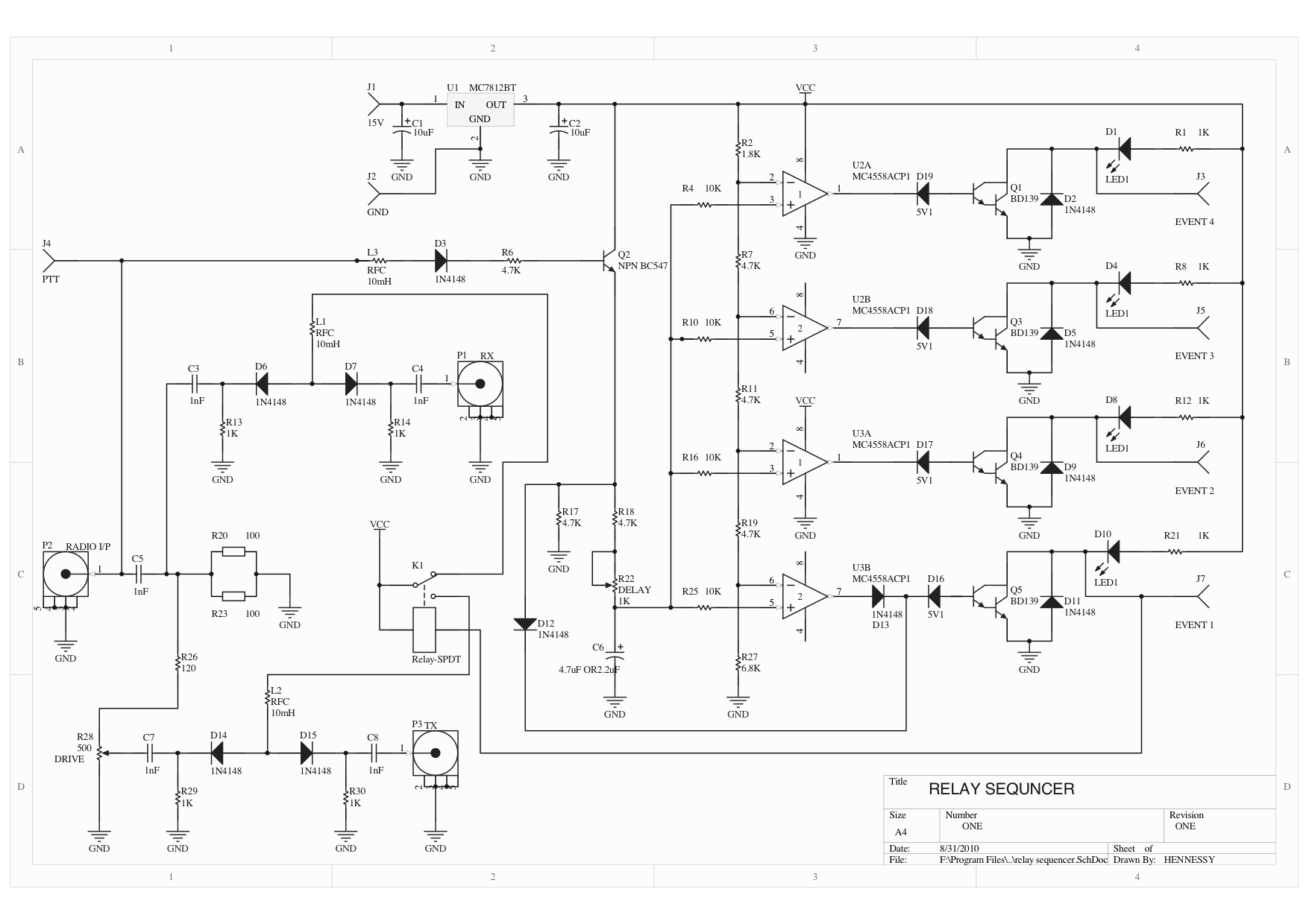
A relay sequencer is utilized in a radio transverter to activate specific stages sequentially after a brief delay. This project outlines the construction of this sequencer, which features a stage that switches the output/input of the driving radio to...

This article continues from the previous one regarding the single character LCD display using an AVR microcontroller. The prior article demonstrated how to display a single letter on an LCD. This article advances the learning process by explaining how...
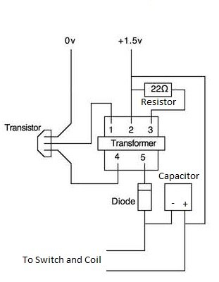
This article explains how to construct a coil gun, a device that launches magnetic projectiles at high speeds using electrical energy. Coil guns do not require explosive propellants, allowing them to be fired indefinitely as long as there is...
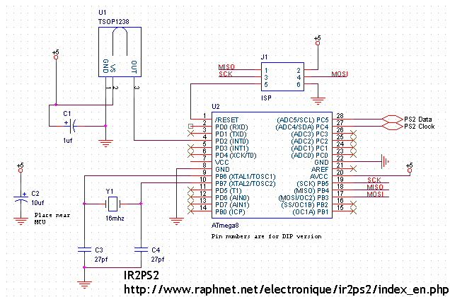
A few years ago, an individual received a small wireless infrared keyboard, part number RC-KB2, intended for use with a Kenwood audio system. The goal was to explore its transmission format to create a small receiver that would enable...
An LCD can display a brief moving message when interfaced with a microcontroller. This project features an AVR-based moving-message display utilizing a 16G-2 LCD that incorporates the HD44780 controller. The 16G-2 LCD is capable of displaying 16 characters per...
As an essential component of an advanced computer science course focused on microcomputer systems, it was determined that students would benefit from the design of a single-board computer system utilizing a widely available microprocessor. This decision led to the...