
Divide-By-N + 1/2 Circuit
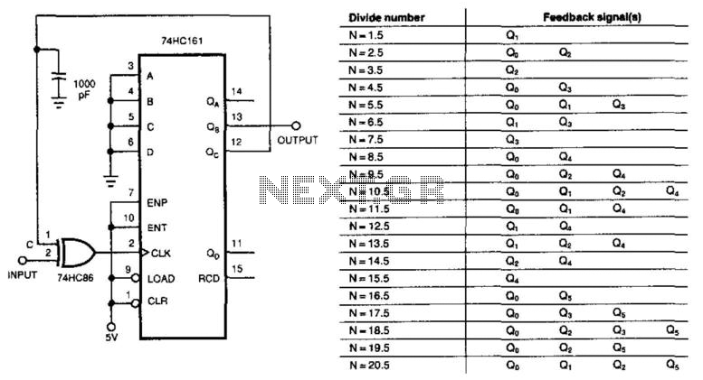
This circuit employs a unique method for signal division, leveraging feedback mechanisms and edge-triggering techniques to achieve precise control over the output. The fundamental operation relies on the ability to change the triggering edge of the 74HC161 counter based on the state of point C. This flexibility allows for dynamic adjustment of the counter's response to the input signal, effectively allowing it to function as a programmable divider.
The 74HC161 is a synchronous 4-bit binary counter that can be configured for various counting applications. By integrating feedback from its output, the circuit can be tailored to achieve specific division ratios. The feedback connections facilitate a form of pulse width modulation, where the output pulse width is modulated based on the changes at point C. This modulation results in a divisor that can be adjusted by varying the number of transitions at point C, thus influencing the effective division ratio.
The ability to generate a division ratio of 3.5 is particularly noteworthy, as it demonstrates the versatility of the circuit design. By utilizing XOR feedback, the circuit can create a counter that operates in a fractional manner, allowing for outputs that do not conform to traditional integer divisions. This capability is essential in applications where precise timing and frequency division are required.
In summary, the circuit's operation hinges on the interaction between the input signal, the state of point C, and the feedback from the counter outputs. It provides a robust solution for achieving fractional division ratios while maintaining the integrity of the input signal. The divided output, accessible at the (m-1) bit of the counter, offers a practical means to utilize the counter's capabilities in various electronic applications. This circuit, instead of dividing by an integer, divides the input signal by +1/2. With the feedback connections exactly as the figure shows, the circuit divides by 3.5. Point C ultimately controls when the input clocks the 74HC1614-bit counter. When C=0, the positive edge of the input triggers the counter. If C=1, the negative edge of the input triggers the counter. Each time that point C changes level, the circuit shortens the output pulse width of the counter by half of an input cycle. Thus, the counter"s divisor depends on how many changes occur at point C during one output period. Although the figure divides by 3.5, feeding back different counter outputs produces different divisors.
Generally, an w-bit binary counter with pure exclusive-OR (XOR) feedback can form an N+ V2 counter, where Arranges from 2m~2 + l/2 to 2m~l-xh. The divided output is available at the m-1 bit of the counter. 🔗 External reference
Related Circuits

This stereo amplifier utilizes the NE5517/A and features an excellent tracking accuracy of 0.3 dB, which is typical. The offset can be adjusted using the potentiometer, Rp. For AC-coupled amplifiers, the potentiometer can be substituted with two 5.1 k...
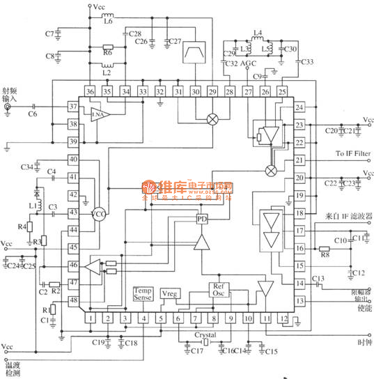
MRFICl505R2 is a 1.575GHz GPS downconverter chip. It integrates a mixer, VCO, PLL, crystal oscillator, A/D converter, loop filter, and other circuits. The MRFICl505R2 IF output frequency is 4.1MHz, with a typical conversion gain of 105dB, an operating voltage...

This page features a circuit that has twenty open collector outputs that turn on one at a time in a continuous sequential manner. The circuit utilizes the 74LSxx family of TTL integrated logic devices. The circuits are designed to...
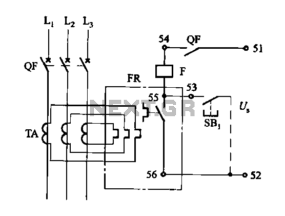
The DK-5A, 5D, and SDb control boxes are equipped with a thermal electromagnetic overcurrent release, as depicted in Figure 6-80. The trip mechanism provides both overload and instantaneous short circuit protection with a long delay feature. In the figure,...
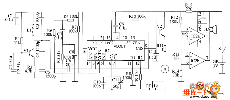
The metal detector circuit consists of a probe oscillator, a PLL (phase-locked loop) circuit, and an audio alarm circuit. The probe oscillator includes a detection coil (L), transistor (V1), and several resistors (R1 to R3) and capacitors (C1 to...
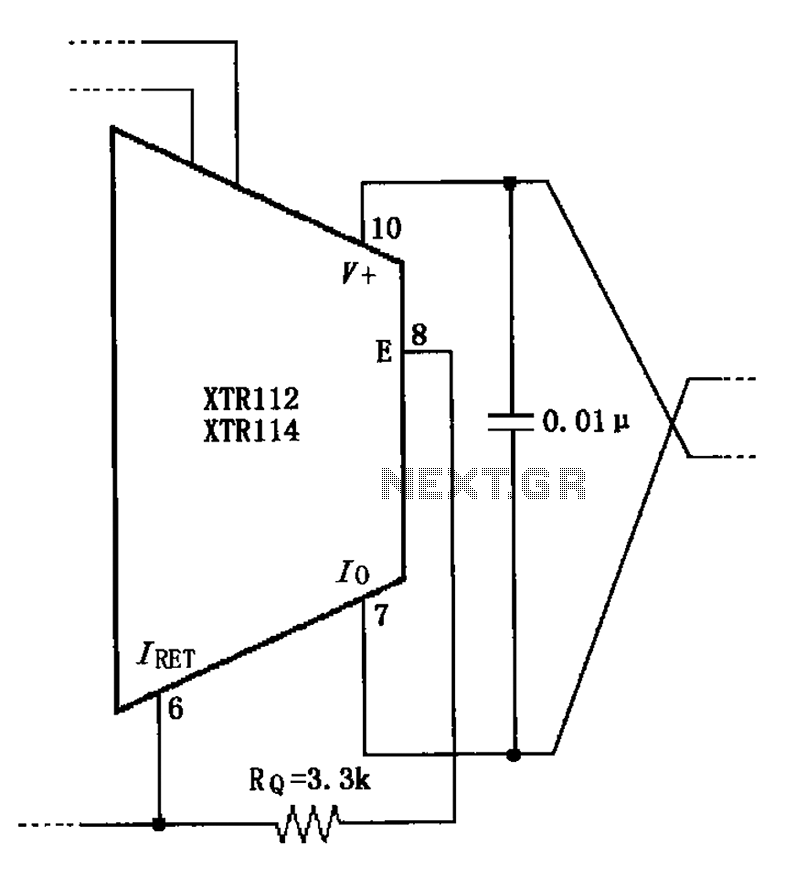
When not using the external transistor Q1, a 3.3k resistor should be connected between the pins and legs. This connection causes internal power dissipation, which will affect accuracy and lead to a decline in performance. The circuit in question involves...
Warning: include(partials/cookie-banner.php): Failed to open stream: Permission denied in /var/www/html/nextgr/view-circuit.php on line 713
Warning: include(): Failed opening 'partials/cookie-banner.php' for inclusion (include_path='.:/usr/share/php') in /var/www/html/nextgr/view-circuit.php on line 713