
20 Output Traffic Light Control Circuit

The circuit does not drive the 74LS145s directly but uses a 74LS107 JK Flip-Flop and four 74LS32 dual input OR gates to control the inputs to the two 74LS145 output drivers. The 74LS107 and 74LS32 are used to create disallowed states in the output drivers alternately. These disallowed states prevent any of the ten outputs on a particular device from being turned ON while the other 74LS145 is counting to ten. This produces a system where only one of the 74LS145s can produce a LOW output state at a time. Essentially, the circuit counts to 10 twice in succession rather than counting to 20 in a single cycle. This approach, although seemingly unconventional, allows the circuit to make economical use of the open collector outputs of the 74LS145s decoder/drivers rather than employing output buffer ICs driven by 74LS138 logic devices.
The TTL logic devices in the circuit require a regulated 5-volt supply and draw approximately 60 milliamps. The outputs of the 74LS145s can be supplied from up to 15 volts with a maximum current of 80 milliamps. A parts list for the 20 Output Sequencing Circuit is provided, with Mouser Electronics part numbers included, although the parts may be available from other sources as well. Suppliers that handle NTE components should be able to obtain the ICs.
The explanations for the circuits on these pages cannot cover every situation on every layout, so experimentation may be necessary to achieve desired results. This is particularly true for circuits such as the "Across Track Infrared Detection" circuits and any other circuit that relies on inputs other than direct electronic signals, such as switches. When using these circuit ideas, it is recommended to request a copy of the manufacturers' data sheets for any components that have not been previously utilized. These sheets contain extensive data and circuit design information that surpasses what any electronic or print article could provide, thereby saving time and potentially preventing damage to the components. These data sheets are often accessible on the websites of the device manufacturers. While the circuits are functional, the pages serve as guides for adaptation rather than comprehensive descriptions of each circuit.
This circuit operates with a sequential output mechanism where each output is activated in a predetermined order, ensuring that only one output is active at any given moment. The use of the 74LS107 JK Flip-Flop allows for the creation of a binary counting mechanism, while the 74LS32 OR gates facilitate the control logic necessary to manage the outputs effectively. This design minimizes the complexity of the circuit while maximizing the efficiency of the output drivers. The careful selection of components, along with adherence to the recommended wiring practices, will enhance the performance and reliability of the circuit in practical applications.This page features a circuit that has twenty open collector outputs that turn on one at a time in a continuous sequential manner. The circuit make use of the 74LSxx family of TTL integrated logic devices. The circuits are designed to drive light emitting diodes or low current, low voltage incandescent lights but can also drive other loads of up to
80 milliamps. As logic circuits go, the 20 Step circuit is fairly simple but due to the high speed nature of the TTL Logic devices used, care must be taken when wiring these circuits. Simply put; The neater the wiring the better. If you would like to make use of these circuits, please take the time to find and read at least the first 2 pages of the manufactures data sheets for the integrated circuits.
Using Google, search for "74ls(part number)" in the first box and "PDF" in the second box on the advanced search page. The circuit does not drive the 74LS145`s directly but uses a 74LS107 JK Flip-Flop and four 74LS32 dual input OR gates to control to the inputs to the two 74LS145 output drivers.
The 74LS107 and 74LS32 are used to create disallowed states in the output drivers alternately. The disallowed states prevent any of the ten outputs on that particular device from being turned ON while the other 74LS145 is in counting to ten. This produces a system where only one of the 74LS145`s is able to produce a LOW output state at a time.
In essence the circuit counts to 10 twice in succession rather than counting to 20 in a single cycle. This may seem like an unusual method but it allows the circuit to make economical use of the open collector outputs of the 74LS145s decoder/drivers rather using output buffer ICs driven by 74LS138 logic devices.
The TTL logic devices in the circuit require a regulated 5 volt supply and draw approximately 60 miliamps. The outputs of the 74LS145`s can be supplied from up to 15 Volts with a maximum current of 80 milliamps.
The following is a parts list for use with the 20 Output Sequencing Circuit. Mouser Electronics part numbers are shown but the parts may be available from other sources as well. Suppliers that handle `NTE` components should be able to get the ICs. The explanations for the circuits on these pages cannot hope to cover every situation on every layout. For this reason be prepared to do some experimenting to get the results you want. This is especially true of circuits such as the "Across Track Infrared Detection" circuits and any other circuit that relies on other than direct electronic inputs, such as switches.
If you use any of these circuit ideas, ask your parts supplier for a copy of the manufacturers data sheets for any components that you have not used before. These sheets contain a wealth of data and circuit design information that no electronic or print article could approach and will save time and perhaps damage to the components themselves.
These data sheets can often be found on the web site of the device manufacturers. Although the circuits are functional the pages are not meant to be full descriptions of each circuit but rather as guides for adapting them for use by others. If you have any questions or comments please send them to the email address on the Circuit Index page.
🔗 External reference
Related Circuits
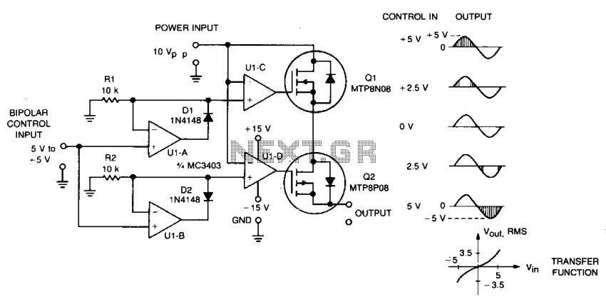
This circuit accepts bipolar control inputs of ± 5 V and provides a phase-chopped output to a DC load (such as a servo motor) of the same polarity as the input. The RMS voltage of the output is closely...
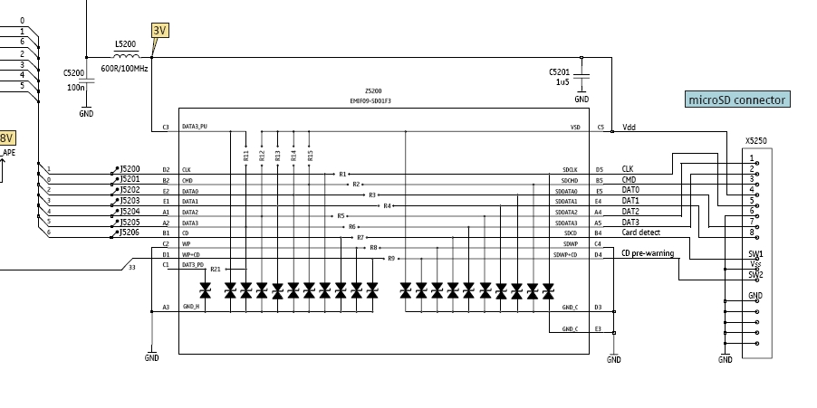
In this tutorial, the functioning of the memory card circuit in mobile phones will be explored. The previous post discussed the pin-outs and types of memory cards utilized in cellular devices. The accompanying block diagram illustrates how the removable...

The system consists of an LK16-5/31 type master controller and a PQY1 Series magnetic control panel, which includes a control circuit. The motor is controlled by limit switches SQ1 and SQ2, which manage the reverse operation. The master controller...
The induction coil detects the magnetic field flux during phone calls, amplifies the signal, and triggers the LED. These circuits are designed for the phone to rest on the pickup coil. The electromotive force (emf) from the bell electromagnets...
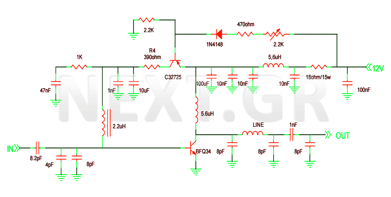
This project involves the construction of a VHF-UHF linear amplifier capable of operating at frequencies ranging from 47 MHz to 740 MHz. It serves as the final output stage for any transmitter functioning within these frequencies. The amplifier utilizes...
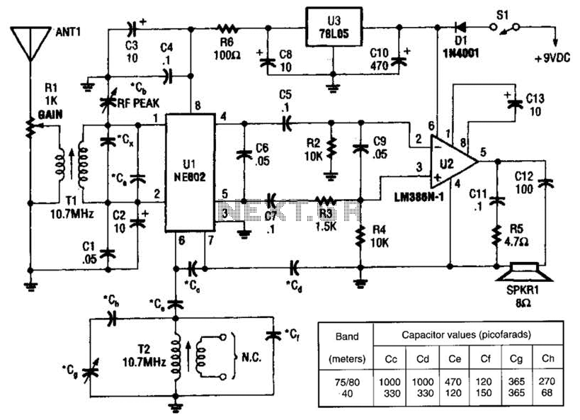
An NEC602 is utilized as a mixer with a zero intermediate frequency (IF) output, while U2 functions as an audio amplifier. This receiver is mainly designed for single sideband (SSB) and continuous wave (CW) signals. T1 and T2 are...