
DIY Audio Function Generator Part 1

The proposed audio function generator circuit will consist of several key components to achieve the desired performance characteristics. The heart of the generator is the Wien-bridge oscillator, which is known for its ability to produce low-distortion sine waves. The #327 lamp serves as a variable resistance element, allowing for the stabilization of amplitude and maintaining low THD. The output from the Wien-bridge oscillator will be fed into a comparator circuit, which will convert the sine wave into a square wave. This square wave will then trigger a ramp generator circuit, designed to produce a linear ramp output. This ramp waveform is advantageous for testing and evaluating various ADC configurations.
The frequency range switch will allow the user to select between three distinct frequency ranges, facilitating operation across a broad spectrum of applications. The inclusion of a 10K potentiometer enables fine-tuning of the output frequency within the selected range, providing flexibility for various testing scenarios. The ramp current source adjustment potentiometer will allow for precise control over the ramp rate, enabling experimentation with different ADC architectures, including single-slope and dual-slope designs.
To enhance usability, the circuit will also feature a +3.3V square wave output, which can be directly interfaced with a frequency counter. This feature negates the need for a dedicated display on the function generator, streamlining the overall design. The combination of these components and features is aimed at creating a versatile and effective audio function generator capable of meeting the requirements of low THD and operational flexibility for RF and ADC testing applications. The anticipated settling time after adjustments, while a consideration, is deemed an acceptable trade-off for the high-quality sine wave output that this design aims to deliver.A simple low end Audio Function Generator. I want to be able to use the Sine Wave output to test ADC resolution and as a base band signal for RF projects and having very Low Total-Harmonic-Distortion (THD) would be nice. So I`ve decided to build my own Function Generator. Most DIY Function Generators I found online start out with a Square Wave Oscillator feed into an integrator to get a triangle wave, then you feed the triangle wave into a wave shaper and you get a rough Sine Wave output. This is similar to a project I built up last year. This method works, but the wave shaped Sine wave isn`t going to have the low THD I was looking for, so I am taking the opposite approach and starting with a Sine Wave Generator based on the #327 Lamp Wien-bridge Circuit to get the low THD.
I`ll then feed that into a Comparator to produce the Square wave; I am then using the Square Wave to turn on/off a ramp generator circuit. I would rather have a ramp output vs a triangle wave. The ramp circuit will let me play around with different single & dual slope ADC concepts later on. I`ve added a +3. 3V Square wave output to be feed into a frequency counter, so I don`t need to bother to add a display to the function generator.
Mine as well make use of the Frequency counter I have for a display, also having a +3. 3V square wave output would be nice for any micro projects later on. I`ll have a Freq. Adjust Pot, Freq. Range switch, Ramp Current Source Adjustment Pot, and an Output Amplitude Adjustment potentiometer. Below is a rough layout of the proposed design: After sketching out the concept drawings my next step was to test the Wien-Bridge Oscillator circuit I was basing this whole design around. I prototyped up the circuit with the Frequency Range Select switch and 10K pot and was pleasantly surprised to see everything worked well.
The three switch selectable frequency ranges I have are: 16Hz to 600Hz, 160Hz to 6kHz, and 1. 6kHz to 60kHz with the 10K potentiometer adjusting the output frequency continuously through the ranges. The one downside with this Lamp based implementation is there is a settling time of several seconds needed after each major adjustment to allow time for the Lamp to thermally settle.
this is an ok tradeoff for me given I should be able to achieve very low 0. 05% or lower THD. 🔗 External reference
Related Circuits
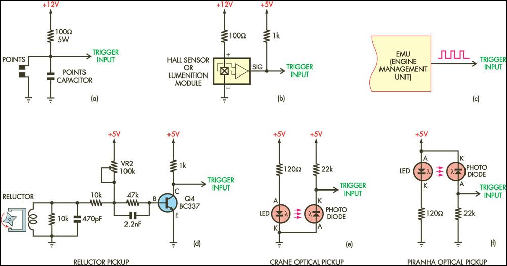
The document provides an extract from another SC article discussing a simple programmable TCI (Transistor Controlled Ignition) that features nearly identical trigger input circuits to the DIY-CDI (Capacitor Discharge Ignition) system. It highlights that the trigger circuits are described...
This project is probably the most ambitious so far, and can be expected to be very expensive. On the positive side, it is also capable of excellent performance, and can be tailored to suit your exact specifications. There are...
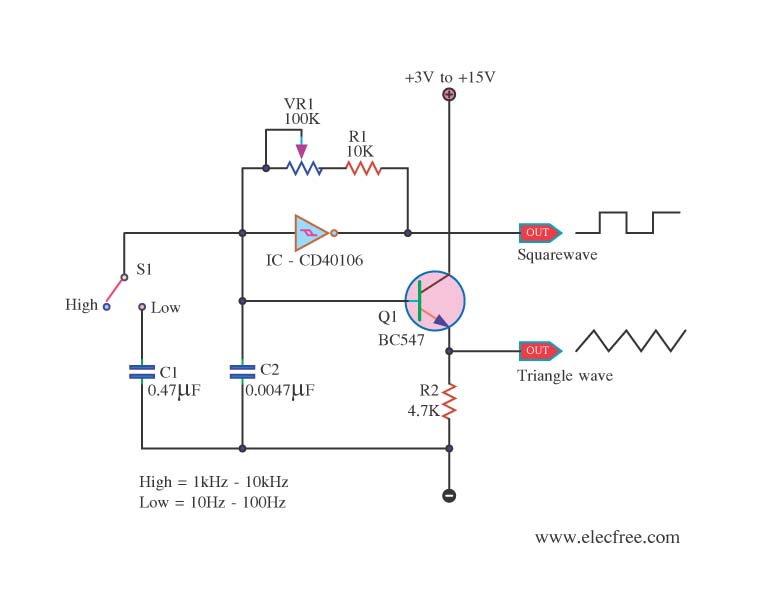
This is a function generator project that can be used as a triangle and square wave generator. The main components include the CD40106, a popular CMOS integrated circuit, and a standard transistor. The function generator circuit utilizes the CD40106, which...
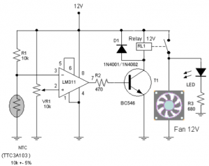
The circuit schematic diagram of a fan speed control system that activates only when necessary. When the transistor heats up, the fan will automatically turn on. The fan speed control circuit operates based on the temperature of the transistor, utilizing...
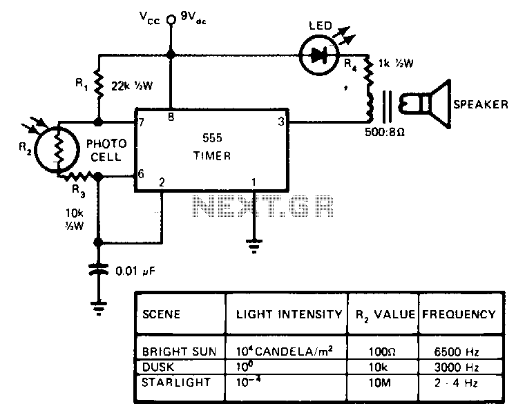
This circuit's frequency of oscillation increases directly with light intensity. The greater the light intensity, the higher the frequency of the oscillator. The 555 timer operates in the astable oscillator mode where frequency and duty cycle are controlled by...
This reference design demonstrates the MAX98400 Class D audio amplifier in a stereo audio docking station application. The demo box is a powered speaker dock that drives a speaker system consisting of 2-inch satellite speakers and a 5-inch subwoofer. The...