
Transistors Function in the fan speed Control

The fan speed control circuit operates based on the temperature of the transistor, utilizing a feedback mechanism to regulate the fan's activation. This circuit typically includes a temperature sensor, a transistor, a fan, and a power supply.
The temperature sensor detects the heat generated by the transistor. As the temperature rises beyond a predetermined threshold, the sensor sends a signal to the transistor, which acts as a switch. When the transistor is activated, it allows current to flow from the power supply to the fan, turning it on. The fan operates at a speed proportional to the temperature, which can be adjusted through resistor values in the circuit.
This configuration not only conserves energy by ensuring that the fan operates only when necessary but also prolongs the life of both the transistor and the fan by preventing unnecessary wear from constant operation. The circuit may also include additional components such as diodes for flyback protection, capacitors for filtering, and potentiometers for fine-tuning the sensitivity of the temperature sensor.
Overall, this fan speed control circuit is an efficient solution for managing heat dissipation in electronic devices, ensuring optimal performance while minimizing energy consumption.the circuit schematic diagram of Fan Speed Control which turns on only when needed. when your transistor getting hot, the fan will automatically . 🔗 External reference
Related Circuits
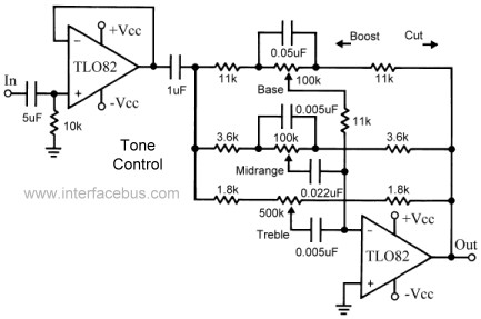
This topic continues the coverage of audio tone controls. The first entry started with a passive tone control circuit using different RC filter configurations and introduced an active filter. The second entry showed a fully designed 2-band active tone...
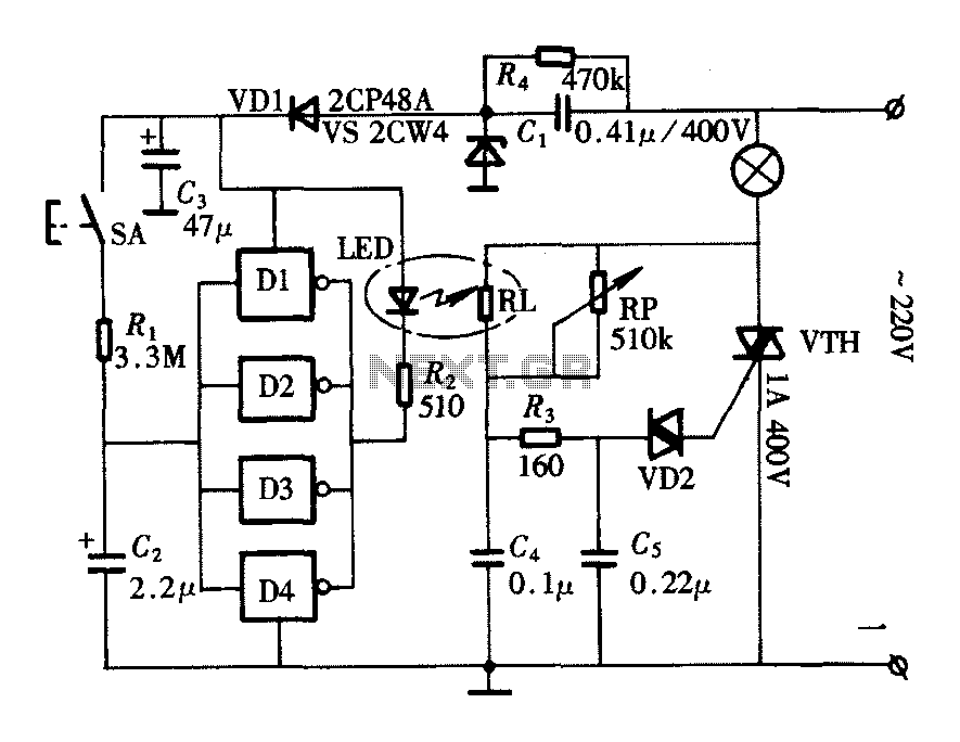
The lighting controller depicted in the figure features a gradual dimming function that prevents sudden brightness changes, which can irritate the human eye and potentially cause damage due to inrush currents. The circuit design includes a six-stage CD4069 inverter...
This circuit controls a load, specifically a DC brushless fan, based on temperature compared to a setpoint. The transducer used is a diode operating in the forward polarization regime. When forward-biased, the forward voltage drop across the diode exhibits...
The schematic depicts standard light bulbs, indicating the possibility that some bulbs may be burned out. It is currently unclear whether the bulbs can be easily replaced. Further inspection reveals that the bulbs in the HVAC control can indeed...
This add-on circuit enables remote switching on/off of battery-operated toy cars using a TV/video remote control handset operating at 3040 kHz. The described circuit utilizes a remote control system to facilitate the wireless operation of battery-powered toy cars. The primary...
The circuit depicted in Figure 3-120 allows for the control of a motor with a capacity of less than the rated current of 5A by using an intermediate relay instead of a contactor. This circuit enables four forward running...