
DOD Overdrive 250 preamp circuit diagram
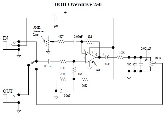
The DOD Overdrive 250 preamp circuit is a notable example of classic guitar effect design, leveraging widely recognized components to achieve a distinct sound profile. The circuit’s use of the 741 operational amplifier establishes a solid foundation for signal amplification, while the inclusion of two diodes at the output stage introduces clipping characteristics that enhance the overdrive effect. This configuration is designed to produce a warm, saturated tone that appeals to guitarists seeking a vintage sound.
The DOD FX75 Flanger circuit, as drawn by Fabian P. Harter, integrates advanced components such as the CD4007 and TL022C, which are essential for achieving the desired modulation effects. The CD4007 serves as a dual complementary pair, facilitating signal inversion and shaping, while the TL022C provides low power consumption and low noise amplification, critical for maintaining audio fidelity in guitar effects.
The MN3007 and MN3101 components are integral to the flanger's operation, allowing for precise delay manipulation and timing control. The MN3007’s bucket brigade architecture enables a range of delay times, contributing to the flanger’s sweeping sound effects.
The discrete JFET preamp design utilizing the 2N5457 transistor is particularly noteworthy for its low noise and distortion properties, making it suitable for high-fidelity applications. This design approach is favored by those who prefer a more analog and less op-amp-centric architecture, providing a unique tonal character and responsiveness.
The PAiA Electronics vacuum tube preamp circuit represents a classic approach to amplification, utilizing the inherent qualities of vacuum tubes to deliver warmth and depth to the audio signal. The circuit configuration, which includes the 4049 CMOS Hex Inverting Buffer and 5532 Dual Low-Noise operational amplifiers, is designed for ease of use and cost-effectiveness, making it accessible for hobbyists and professionals alike.
In summary, these circuits exemplify a blend of traditional and modern design philosophies in guitar effects, showcasing a range of components and configurations that cater to diverse sonic preferences. Each circuit serves a unique purpose, contributing to the rich landscape of guitar amplification and effects processing.This is the DOD Overdrive 250 preamp circuit diagram. The DOD Overdrive 250 is Yet Another 741 With Two Diodes On The Output channel. It is almost exactly the same as the MXR Distortion Plus, and a number of other units. Download the DOD Overdrive 250 circuit in PDF file: » Download Link This is the circuit diagram of DOD FX75 Flanger guitar effe ct pedal. The circuit drawn by Fabian P. Hartery Components CD4007 dual complementary pair with inverter; (RCA) TL022C low power dual operating amplifier; (texas instruments) MN3007 audio signal delay, 1024 stage low noise BBD (5. 12-51. 2 msec delay) MN3101 clock generator for Bucket Brigade Device/BBD. Designed by Don Tillman, this guitar pre-amp circuit design is dedicated for people who don`t like op-amps.
This circuit is a discrete JFET pre-amp design, use 2N5457 as the main component. It has low noise, low distortion, low feedback, overloads gracefully, is small, etc. Overall gain is 3db (2X) or so. It uses about 1/2. This is a simple and low cost Tube Head Vacuum Tube pre-amp circuit designed bu PAiA electronics: Vcc - Pin 1 IC1 +12v - Pin 8 IC2, IC3, IC4 -12v - Pin 4 IC2, IC3, IC4 Ground - Pin 8 IC1 IC1 - 4049 CMOS Hex Inverting Buffer IC2, 3, 4 - 5532 Dual Low-Noise. 🔗 External reference
Related Circuits
The receiver provides two TV signals, one for the living room and another for the bedroom, along with a satellite receiver. Watching television in the bedroom is convenient in Taiwan; however, when watching television in the living room, it...
A steam engine powered carousel project that utilizes the Joule Thief circuit. The project involves the design and construction of a carousel that is powered by a steam engine, showcasing the principles of mechanical motion and energy conversion. The Joule...
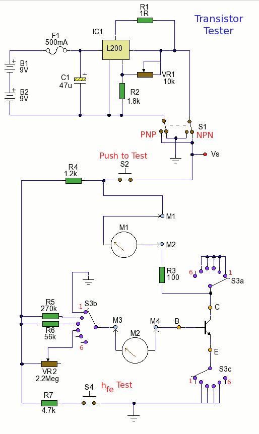
Using the tester is straightforward. Begin with the power off and insert a transistor into the test socket. Set switch S1 for either NPN or PNP configuration and rotate switch S3 to the desired test position. Adjust variable resistor...
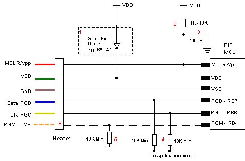
Microchip does not recommend any specific circuit for In-Circuit Serial Programming (ICSP). Various diagrams exist for different tools, such as Pro Mate and PICKit2, which feature similar circuitry with minor variations. Some schematics may suggest resistor values that are...
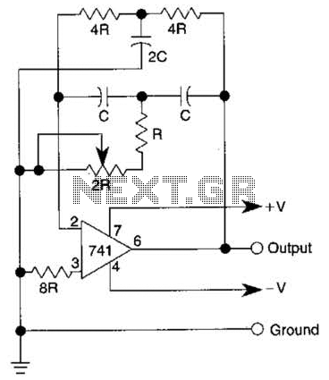
The quality of the sine wave depends on how closely the components in the twin-T network are matched in the operational amplifier's feedback loop. The twin-T network is a type of filter circuit commonly used in audio applications, signal processing,...
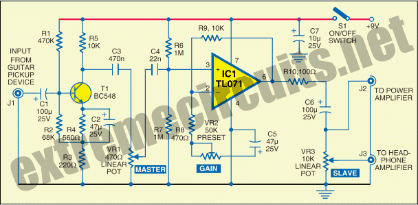
The circuit diagram of a guitar preamplifier is designed to accept any standard guitar pickup and features two signal outputs. A typical example of a pickup attached to a guitar headstock is illustrated. The pickup device consists of a...