
Transistor tester circuit
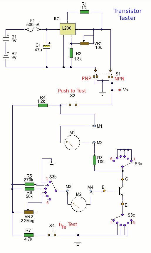
The described circuit is a transistor tester designed to measure key parameters such as DC current gain (hFE) and small-signal current gain (hfe) of transistors. It includes a test socket for inserting the transistor, a power supply adjustable via VR1, and a series of switches (S1, S2, S3, and S4) for selecting transistor type and test conditions. The circuit utilizes a multimeter to measure various current levels, enabling users to evaluate the transistor's performance under different configurations and operating points.
The setup allows for the measurement of leakage currents, base currents, and collector currents, with the ability to adjust for different transistor types (NPN or PNP) and conditions (silicon or germanium). The design accommodates a range of power supply voltages and currents, making it versatile for various testing scenarios. The inclusion of variable resistors (VR1 and VR2) provides flexibility in establishing the necessary operating points for accurate measurements.
In practice, the circuit's effectiveness hinges on proper calibration and the use of quality components to ensure reliable readings. The use of a digital multimeter enhances measurement accuracy, while the straightforward design facilitates ease of use for electronics enthusiasts and professionals alike. Overall, this transistor tester is an essential tool for evaluating and characterizing transistors in various electronic applications.Using the tester is easy, starting with power off, insert a transistor into the test socket. Set S1 for NPN or PNP androtate S3 to the required test position. Rotate VR1 so the desired collector emitter voltage. Pressing S2 now allows the measurement of hFE to be made. Pressing S2 and S4 allows hfe to be measured. More detailed usage now follows. With S3 in position 1, insert a transistor into the test socket and set S2 for NPN or PNP. M3 and M4 need to be shorted and a multimeter set to DC microamps between M1 and M2 now allows collector base leakage current to be measured. With silicon transistors, you may not see a reading at all, but germanium transistors have leakage current which can be measured.
Set S1 for NPN or PNP and rotate S3 to position 2. Rotate VR1 so the power supply reads 6 Volt between terminal Vs and ground. Place a shorting link across M3 and M4 and a digital multimeter set to measure DC lamps across M1 and M2. Pressing S2 now allows the measurement of hFE to be made. This will be the meter reading / 20 uA. Set S1 for NPN or PNP and rotate S3 to position 3. Rotate VR1 so the power supply reads 6 Volt between terminal Vs and ground. Place a shorting link across M3 and M4 and a digital multimeter set to measure DC milliamps across M1 and M2.
Pressing S2 now allows the measurement of hFE to be made. This will be the meter reading / 100 uA. Set S1 for NPN or PNP and rotate S3 to position 4. The parameter hFE varies with different collector currents and temperatures. VR1 and VR2 allow you to set up different operating points. Suppose you have a circuit where a transistor is run from a 15 Vdc supply and base current is 15 uA. First set VR1 so the power supply reads 15 Volt between terminal Vs and ground. Place a shorting link across M1 and M2 and a digital multimeter set to measure DC microamps across M3 and M4. Press S2 and adjust VR2 until 15 uA is measured between M3 and M4. Now release S2, short terminals M3 and M4, remove the link across M1 and M2 and set the meter to read DC milliamps.
Pressing S2 now allows the measurement of hFE to be made. This will be the meter reading / 15 uA (or whatever base current you choose). With S3 in position 5, insert a transistor into the test socket and set S2 for NPN or PNP. M3 and M4 need to be shorted and a multimeter set to DC microamps between M1 and M2 now allows collector emitter leakage current to be measured. With silicon transistors, you may not see a reading at all, but germanium transistors have leakage current which can be measured.
The value of the small signal current gain hfe can also be measured with this circuit, for base currents of approximately 20uA, 100uA or any particular operating point. Proceed as in the previous steps for measuring DC current gain and with S3 at position 2, 3, or 4. The voltage Vs should be set to 6 Volt, a short across meter terminals M3 and M4 is required then press S2 and read the current on the meter across terminals 1 and 2.
This reading will be called IC1. Now keeping S2 pressed, also press S4, record the reading, this is measurement IC2. You can also measure hfe at any operating point within the voltage and current range of the power supply. The power supply can deliver 18 Volts at up to 500mA. Larger currents will drain the batteries so a bench power supply would be recommended. To measure hfe at a VCE of 12 Volts and collector current 1 mA. First adjust VR1 so that the supply Vs is 12 Volt. Short M3 and M4, press S2 and connect a multimeter to M1 and M2 and adjust VR2 to read 1 mA. Now release S2, short M1 and M2 and remove the short on M3 and M4 and set your meter to microamps and measure the current.
Record both values of base and collector current. Now press S2 and S4 and measure both collector and base currents again. The value of hfe is the difference in collector current divided by the difference in base current. The small signal AC current gain is achieved by changing the value of the base current. When S4 is pressed, the input voltage is reduced by the fraction R7 / (R4+R7) which reduces the input base current. hfe is the change in collector current divided by the change in base current. The base current which is calculated as follows: The difference in base current is therefore 92. 6uA - 72. 8uA = 19. 8uA This value is then used as the denominator forthe larger change in collector current, as in the previous section.
In practice, the difference between hFE and hfe is often so small that one value can be substituted for the other. Data sheets invariably quote the value for the dc current gain hFE, the parameterhfe is the ac quantity and decreases also at higher frequency.
As this circuit measures the change in base current at dc the value of hfe will only be approximate at low frequencies up to 1kHz. To measure hfe at a particular frequency, then a signal generator would be required and the meter set to measure ac base and collector currents.
Although simple, the wiring of the switch can be troublesome, and if you already have a variable power supply, multimeter and a breadboard, then you can set up the circuit as shown below: In my test transistor, a BC109C Base current was 94. 6 uA. The power supply was set at 6V and a 56k and 1. 2k resistor wired in series. Next the collector current was measured, see below: 🔗 External reference
Related Circuits
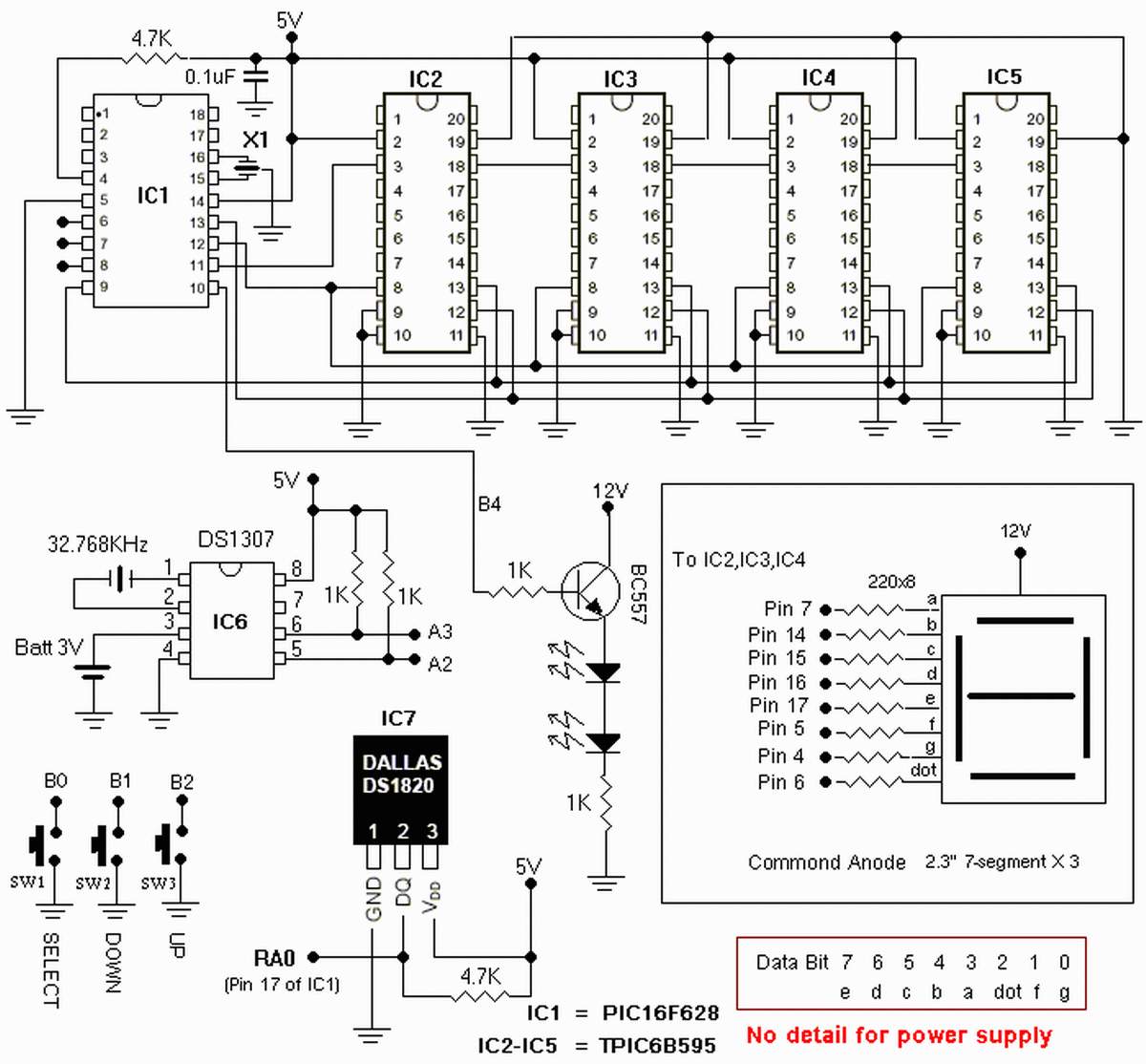
The clock is based on the PIC16F877 microcontroller from Microchip Technology Inc., which performs all of the logic necessary to decode the MSF signal and display the time on twelve 7-segment displays. The circuit design incorporates the PIC16F877 microcontroller, a...
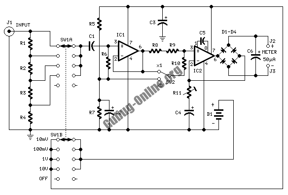
This design circuit is used to activate circuitry and an analog meter for sensitive DC current measurements. A subsequent inquiry raised the possibility of measuring AC microamperes, which inspired the idea for this circuit. The circuit is designed to facilitate...
Most circuits utilize a 5 V regulated power supply for microcontrollers and sensors, as 8-bit microcontrollers operate efficiently at this voltage. The 5 V supply is adequate for powering white LEDs, thus the specific voltage requirements of individual LEDs...
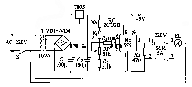
The NE555 time base circuit with an AC solid-state relay (SSR) can function as an automatic light switch circuit. The circuit diagram illustrates that during the day, the incandescent light is turned off due to the influence of the...
This small circuit is designed to verify the basic functionality of an infrared remote control unit. The circuit utilizes a straightforward approach by connecting a piezo buzzer directly to an IR receiver integrated circuit (IC). This configuration is as...
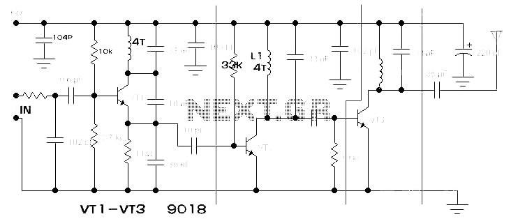
The components available were utilized to create a long-range FM radio transmitter operating within the 88-108 MHz band, designed for playing music. The circuit includes a power section that rectifies mains voltage to provide a stable 12V DC for...
Warning: include(partials/cookie-banner.php): Failed to open stream: Permission denied in /var/www/html/nextgr/view-circuit.php on line 713
Warning: include(): Failed opening 'partials/cookie-banner.php' for inclusion (include_path='.:/usr/share/php') in /var/www/html/nextgr/view-circuit.php on line 713