
Domestic And Industrial

This inexpensive two-way intercom provides a simple method for two-way communication, allowing for both sending and receiving signals. The circuit is built around timer IC555 (IC1) and low-power audio amplifier IC386 (IC2). The design consists of two parts, with the circuit diagram for one part shown in the figure. The output of one unit is connected to the input of the other unit, with the two parts linked via three connection points: 'S' for supply, 'O' for output, and 'G' for ground. When switch 'S1' is pressed, IC1 is triggered, and since IC1 is configured in astable mode, it functions as a tone generator or oscillator. The oscillations generated at output pin 3 are routed to bypass input pin 7 of IC2. Communication sound signals are captured by a condenser microphone connected to audio input pin 3 of IC2. These signals are amplified by audio amplifier IC2, with the amplified output at pin 5 being sent to a loudspeaker through coupling capacitor C1. The unit can be muted by pressing switch S2. The components listed are for one side only; the other side of the unit requires the same components, effectively doubling the total component count except for the power supply. A three-core shielded wire, approximately 4-10 meters in length, can be used for connections between the two units.
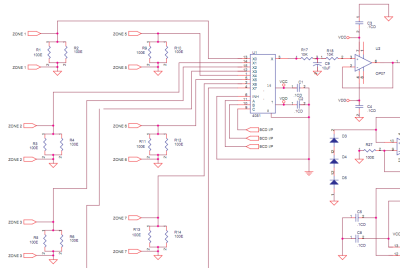
The concept of purifying air is addressed, highlighting the adverse effects of industrial developments on air quality, leading to various health issues. This small unit is designed to counteract these disorders by restoring ionic balance in the air. Pure air contains positive and negative ions in an approximate 1:1 ratio, while polluted air tends to have a deficiency of negative ions and an excess of positive ions. The principle employed involves applying a high negative voltage, several kilovolts, to achieve the desired air purification effect.This is a simple and inexpensive clap operated switch, which uses only four transistors and resistor/capacitor network. The name of the project itself suggests its application. It can be used for level control in hydroculture project. Also for kitchen purpose like detecting the level of water in washing machine. The main feature of this circuit is that it shows each level in meaningful English letters. It displays letter E` for Empty, `L` for Low, `H` for Half, `A` for Above Average and F` for Full Tank. The sensors for each level are immersed in tank. Their other ends get interconnected through four NOR gates, which uses IC1. The output is then given to IC2, which is BCD to seven- segment display driver IC. The level of fluid is indicated on 7- segment display. As shown in the circuit diagram, according to the level of liquid in tank, IC1 triggers each NOR gate.
The output of each NOR gate in IC1 is applied to BCD input of IC2. When tank is low, the logic of four NOR gates in IC1 gives BCD logic as 1010. Their logics are applied to BCD inputs of IC2. Hence IC2 drives 7- segment display according to the BCD Code present at inputs. For low level BCD logic is 1010`. For this logic, display will indicate L`. As the level increases, BCD logic changes, and display will indicate accordingly. That is H` for half and A` for above average. You can see the code generation table or logic table. Note that there is no display pattern like E` or F` available from IC2. Therefore to obtain these pattern transistors T1 and T2 are used. These transistors blank out the unnecessary segments from 7- segment display. It can be seen that the letter `E` is generated by blanking b` and c` segments while it decodes digit 8`. Letter F` is obtained by blanking segment b` while it decodes letter P`. This inexpensive two way intercom provides a simple way by which we can communicate in two ways i. e. send a signal as well as receive a signal. The circuit is build around timer IC555 (IC1) and low power audio amplifier IC386 (IC2). The circuit is designed in two parts. Here the circuit diagram of one part is shown in figure. The output of one unit is given to the input of other unit. The two parts are connected by three way wire connection points. These points are denoted by `S` for supply, `O` for output and `G` for ground. When switch `S1` is pressed, IC1 gets triggered. Hence IC1, which is connected in astable mode, acts as a tone generator or oscillator. These oscillations generated at output pin3 are given to bypass input pin7 of IC2. The sound signals generated due to communication are received by condenser mic connected at audio input pin3 of IC2.
These signals are amplified by audio amplifier IC2 and the amplified output generated at pin5 is given to Loudspeaker through coupling capacitor C1. We can mute the unit by pressing switch S2. The components mentioned in the part list are only for one side. The other side of the unit uses the same components. Hence twice the components mentioned in the part list should be used except power supply. Three Core shielded wire of about 4-10 meters can be used for connections between two units. Today the fresh air` can only be imagining. Because, nowadays due to the big industrial developments, the air becomes so polluted that most of the people have to suffer from lot of diseases.
But now because of the magic of this small unit, you may say bye-bye to all of these disorders. Although it has lot of advantages, it is a very simple and inexpensive circuit that the people can use it very easily for several years. Pure air has positive and negative ions in 1:1 ratio approximately. Air becomes polluted due to the ionic imbalance. Ionic imbalanced air has less negative ions and more positive ions. The idea mainly employs here is to apply a high negative voltage, several KV in fact, to 🔗 External reference
Related Circuits
This is a status panel driver circuit. This circuit is used to turn on lamps or LEDs in a graphic panel that represent faults, actions, and the status of an application. The status panel driver circuit is designed to control...
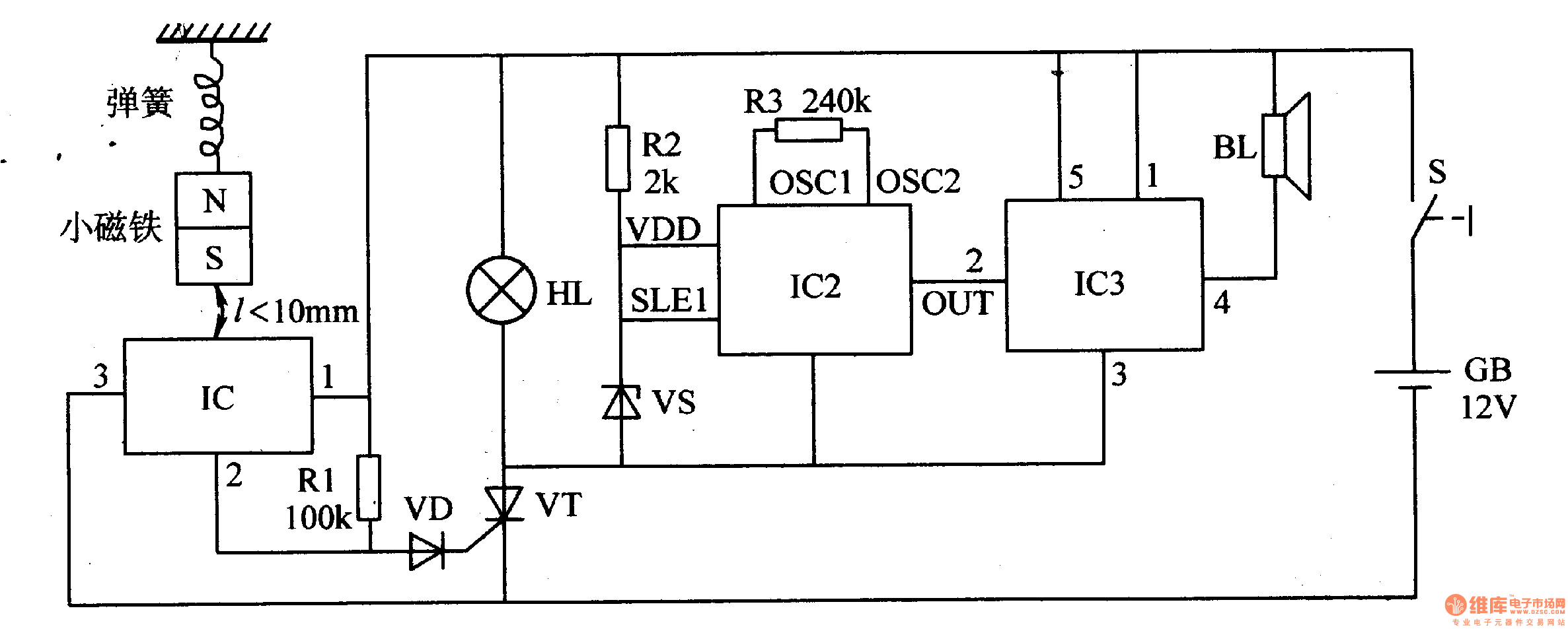
When the switch is activated, the seismic alarm enters a detection mode. In the absence of an earthquake, pin 3 of IC1 outputs a low signal, resulting in the disconnection of VT, which keeps the alarm circuit inactive. Upon...
There are three controls that need to be adjusted for a proportional flow controller to function correctly. This process requires practice, and the experience gained can lead to stable control of the flow or velocity of a fluid. The...
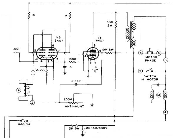
The motor control chassis lacks a coaxial input, raising doubts about the presence of composite sync, particularly given the length of the cables (5 or 6 feet), which may eliminate the possibility of a sync pulse for the red...
This is a personal website showcasing various projects developed during spare time, many of which are related to electronics and Linux. The website itself is one of these projects. It also features a section with pictures from places visited...
Traditionally, high-quality reception of Very Low Frequency (VLF) natural radio signals has required traveling to remote locations far from civilization to find an environment free of interference from artificial radio signals. Many attempts have been made to hike into...