
Domestic Seismic Alarm
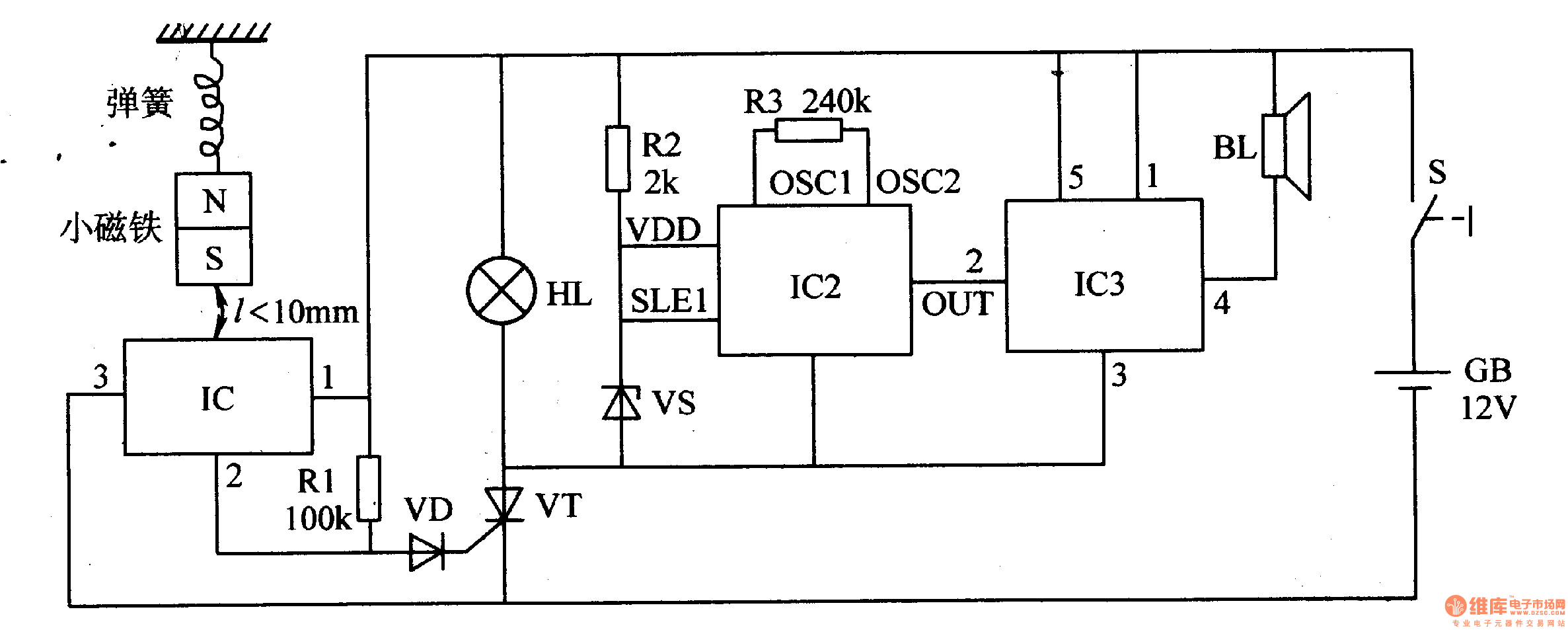
The seismic alarm circuit consists of several key components that work together to detect seismic activity and trigger an alarm. The core of the system is IC1, which serves as the primary detection unit. When the switch is turned on, it enables the detection mode, allowing the circuit to monitor for seismic events.
In its idle state, when no earthquake is detected, IC1's pin 3 remains low, ensuring that VT (which may represent a relay or transistor) is not activated. This state prevents any current from flowing through the alarm circuit, keeping the system in a standby mode. The magnet is positioned close to IC1, maintaining a stable state.
Upon the detection of seismic activity, the magnet's movement causes it to shift vertically. This movement alters the magnetic field around IC1, prompting pin 3 to switch to a high state. This transition activates VT, allowing current to flow through the circuit and illuminating HL, which likely serves as a visual indicator of an alarm condition.
With VT activated, additional integrated circuits IC2 and IC3 come into play. IC2 is responsible for generating an audio signal in response to the detected seismic activity. This signal is then sent to IC3, which functions as an audio amplifier. IC3 boosts the sound output from IC2, ensuring that the alarm sound produced by BL (the buzzer or speaker) is loud enough to alert individuals in the vicinity of the seismic event.
Overall, the circuit is designed to provide a reliable alarm system for detecting earthquakes, combining visual and auditory signals to ensure effective communication of the alarm condition. The integration of multiple ICs allows for efficient processing of seismic signals and amplification of the alarm sound, enhancing the system's responsiveness and reliability.When the switch is on, the seismic alarm isin detection condition. When there is no earthquake, IC1`s pin 3 outputs low level and VT is disconnected. The alarm circuit does not work. When there is an earthquake, the magnet will move vertically. When it is away from IC1, IC1`s pin 3 outputs high level and VT is connected. HL is illuminated. IC2 and IC3 begin to work. When the sound signal output by IC2 is amplified by IC3, BL will make an alarm sound. 🔗 External reference
Related Circuits
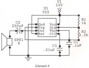
This circuit features an astable oscillator constructed around a 555 timer, generating an alarm tone of 1.8 kHz, which directly drives a speaker. It serves as a fundamental alarm circuit that can be utilized in various projects. Although the...
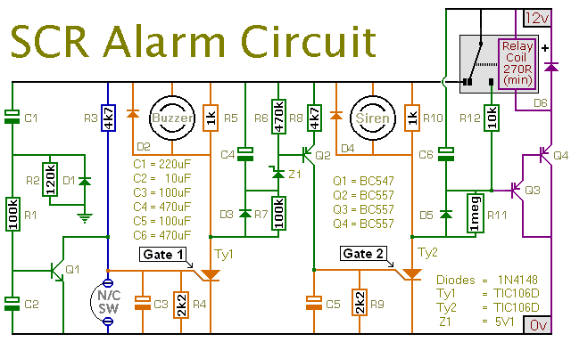
This is a simple SCR-based burglar alarm circuit. Its features include automatic exit and entry delays, along with a timed bell cut-off and reset. It is designed to be used with standard types of normally-closed input devices such as...
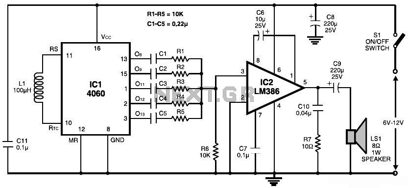
This document presents a simple schematic of a multitone siren alarm circuit. The multitone siren is effective for reverse horns, burglar alarms, and various other applications. It generates five distinct audio tones, making it significantly more attention-grabbing than a...
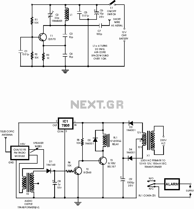
This circuit is a wireless car alarm system that consists of two modules: a transmitter and a receiver. It operates on FM radio waves and is suitable for vehicles with a 6-12V DC power supply. A voltage stabilizer can...
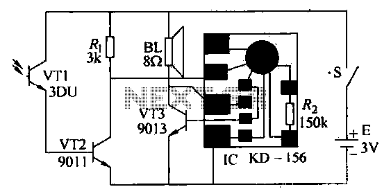
After the gas stove ignition, closing switch S, the circuit is operational. The phototransistor VT1, exposed to flame, remains in a low resistance state. This causes transistor VT2 to enter saturated conduction. Transistor VT3 and the integrated circuit (IC)...
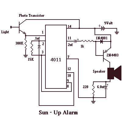
The Sun - Up Alarm can be used to provide an audible alarm for when the sun comes up or it can be used in a dark area and detect when a light comes on. It can also be...
Warning: include(partials/cookie-banner.php): Failed to open stream: Permission denied in /var/www/html/nextgr/view-circuit.php on line 713
Warning: include(): Failed opening 'partials/cookie-banner.php' for inclusion (include_path='.:/usr/share/php') in /var/www/html/nextgr/view-circuit.php on line 713