
Door electronic lock with Keypad

The electronic lock circuit described is a 7-digit code-based locking mechanism that utilizes a series of components to ensure secure access control. The core of the circuit is the integrated circuit IC1, which is a 4022 decade counter. This IC is responsible for counting the input signals from the push-button switches (S1-S10) that represent the digits of the code. Each switch corresponds to a specific digit, and the sequence must be entered correctly without any delays for the system to recognize the input.
The circuit employs a series of resistors (R1-R14) and capacitors (C1-C3, C2) to manage the timing and signal integrity. The resistors R1-R7, for instance, are configured to provide pull-up or pull-down functionality, ensuring that the inputs to the IC are stable during operation. R12, a 220 kOhm resistor, is likely used to limit current and protect the IC from overcurrent conditions.
When the correct sequence of keys is pressed, the output Q7 of the IC is activated for approximately 4 seconds. This output drives the transistor Q2 (BD679), which can control a relay that ultimately opens a door or activates another circuit. The relay provides the necessary isolation and power handling capability to control larger loads that the circuit might need to operate.
Additionally, the circuit includes a visual indicator in the form of a red LED (D3), which illuminates when the lock is activated, providing an optical clue of the system's status. The diodes D1 and D2 (1N4148) are used for flyback protection across the relay to prevent voltage spikes when the relay is de-energized.
The flexibility of the circuit is highlighted by the ability to change the code. By altering the connections between the outputs of IC1 and the switches, a different 7-digit code can be implemented without significant redesign. This adaptability is crucial for maintaining security, as it allows users to modify access codes periodically.
Overall, this electronic lock circuit represents a robust and straightforward solution for secure entry systems, combining basic electronic components to create a reliable locking mechanism.It is a relatively simple circuit of electronic lock of safety with code of 7 digits. It should is given attention in the time that will be stepped the keys, that shape code and it does not exist it delays. With the right step of keys and if code is right then is activated exit Q7 for roughly 4 seconds, driving the transistor Q2, which with the line can drive one relay, for the opening of door, or any other circuit.
With LED D we can have optical clue of activation. The code of circuit, as it has been given have been:1704570 but can change, if we change the connections between in the exits of IC1 and the switches. Part List R1-7=4.7Kohm R12=220Kohm D3=RED LED 3mm R8=15Kohm R14=1.2Kohm IC1=4022 R9=1Mohm C1-3=100nF 100V Q1=BS170 R10-13=10Kohm C2=4.7uF 25V Q2=BD679 R11=100ohm D1-2=1N4148 S1-10=Push button or keyboard 🔗 External reference
Related Circuits

This electronic cricket is a gift for children. This simple battery-powered circuit can be utilized to play cricket matches with friends. Each LED in the circuit... This electronic cricket circuit is designed as an engaging and interactive toy for children,...
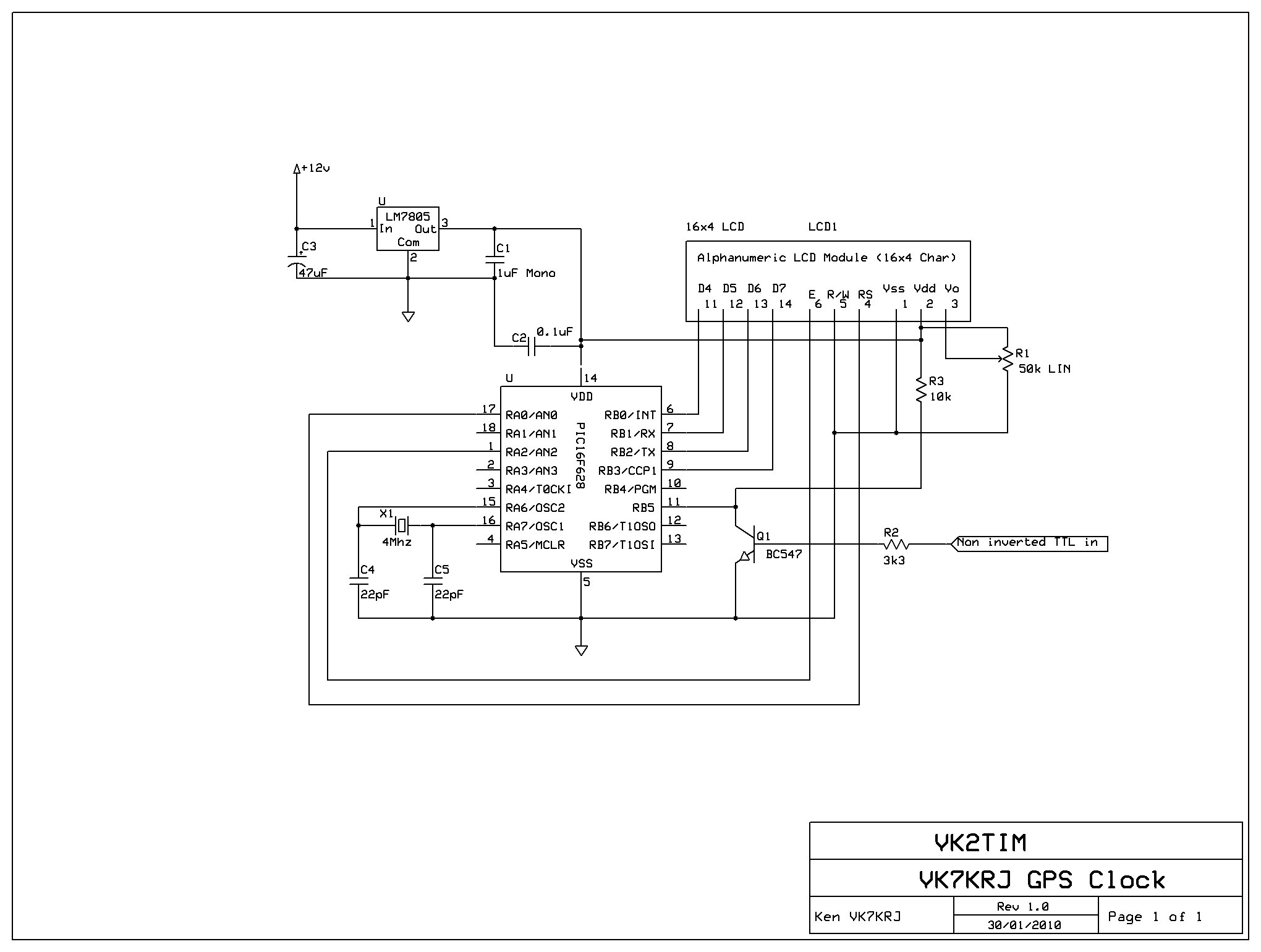
This project is a GPS-based clock that displays the current date, automatically adjusts for daylight saving time, shows current speed, maximum speed, and present heading in degrees relative to true north. The original firmware and concept were developed by...
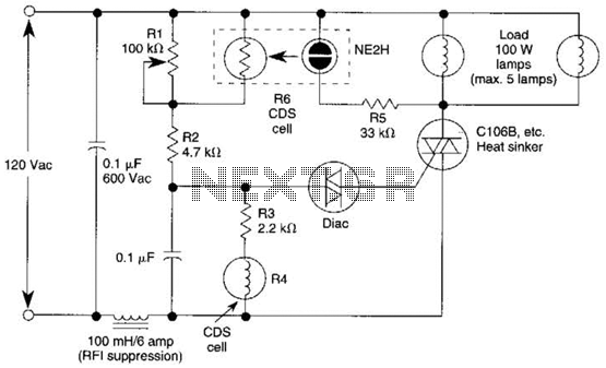
A neon bulb and a CdS photocell are enclosed in a light-tight enclosure to form an optocoupler. A diac/triac combination is employed to create a snap-switch effect. A second CdS photocell serves as the primary sensor. As darkness approaches,...

A simple 16-volt switching power supply circuit can be constructed using the provided diagram, which is based on the MAX668 constant-frequency, pulse-width modulating (PWM), current-mode DC-DC controller. This integrated circuit is designed for a wide range of DC-DC conversion...
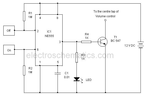
This touch-controlled musical bell circuit generates a musical tone whenever someone touches the designated touch point (TP). The circuit operates using two AA batteries and produces sufficient sound output. It utilizes the UM3481 integrated circuit, which is commonly employed...

The schematic illustrates the design of a circuit that measures the resistance of the skin and transforms it into a functional switching signal. This circuit typically employs a resistive sensor, often referred to as a skin resistance sensor or galvanic...