
Outdoor Light Controller Circuit

The described circuit utilizes an optocoupler design that effectively isolates the control signal from the load while providing the necessary switching action. The neon bulb serves as an indicator and light source, while the CdS photocells function as light sensors, detecting ambient light levels. The first CdS photocell, enclosed within the light-tight enclosure, is responsible for detecting darkness and initiating the switching process.
The diac and triac configuration is crucial for achieving the snap-switch effect, where the triac remains in a conductive state until the current drops below a certain level. This allows for stable operation and prevents flickering of the neon bulb as it turns on and off. The second CdS photocell, acting as the main sensor, provides feedback to the circuit, allowing it to respond dynamically to changes in light conditions.
As ambient light decreases, the resistance of K4 rises, prompting the diac to activate the triac when the light level falls below a predetermined threshold. This triggers the neon bulb to illuminate, which consequently reduces the resistance of R6. The reduced resistance facilitates the diac's triggering of the triac, ensuring that the load receives power.
In the morning, as light levels increase, the resistance of K4 decreases, leading to the triac being turned off when the light exceeds the threshold. This results in the neon bulb extinguishing and the SCR deactivating, effectively completing the light-sensing circuit. The design is efficient for applications such as automatic lighting systems or dusk-to-dawn switches, where the circuit can control electrical loads based on ambient light conditions without manual intervention. A neon bulb and a CdS photocell enclosed in a light-tight enclosure form an optocoupler. A diac/triac combination is used to provide the snap- switch effect. A second CdS photocell acts as the main sensor. As darkness approaches, the resistance of K4 begins to increase. At a threshold level, the ciiac triggers the triac and causes the neon bulb to light. This reduces the resistance of R6, causing the diac to trigger the triac, which lights the neon bulb and provides power to the load. As morning light comes up, the process is reversed. The neon bulb goes out and the SCR turns off.
Related Circuits
Here is a handy zener diode tester which tests zener diodes with breakdown voltages extending up to 120 volts. The main advantage of this circuit is that it works with a voltage as low as 6V DC and consumes...
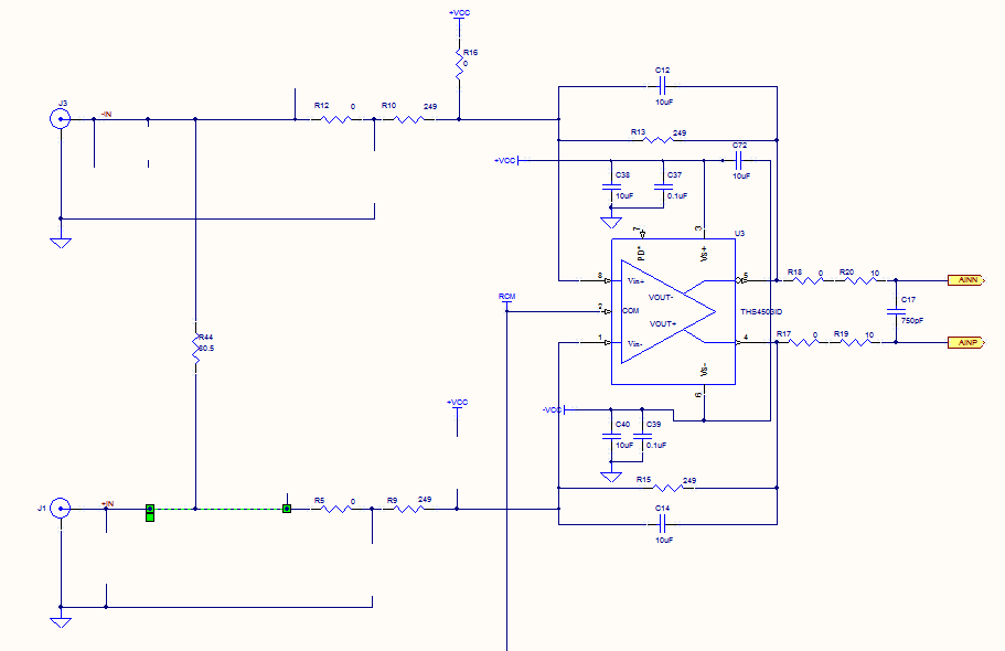
Prior to the test point, there is an AD744 operational amplifier with its output connected to a 10nF capacitor. Following this, a 1kΩ resistor connects to ground. From the junction where the capacitor and resistor meet, a 4.7kΩ resistor...

The circuit utilizes the LM324 as a band-pass filter and the LB1405 as a driver for a five-band spectrum display. The selected frequency harmonics are centered at 100 Hz, 330 Hz, 1 kHz, 3.3 kHz, and 10 kHz. The...
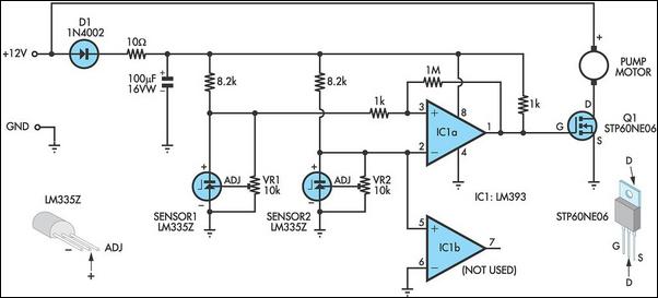
This circuit optimizes the operation of a solar hot water system. When the water in the solar collector is hotter than the storage tank, the pump runs. The circuit comprises two LM335Z temperature sensors, a comparator, and a MOSFET....
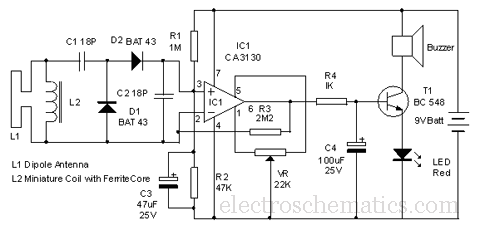
This circuit is designed to detect microwave sources, such as microwave ovens, satellite communication devices, and mobile phones. It provides audio-visual indications when microwaves in the gigahertz band are detected. Microwaves are a form of electromagnetic radiation with frequencies...
The controllable multivibrator, as illustrated in figure 14-40, consists of a 555 timer along with resistors RA, RP1, and capacitor C1. The oscillation frequency is influenced by the control voltage applied to pin 5. This control voltage is determined...