
doorphone intercom
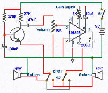
An 8-ohm speaker is employed in this circuit as a dual-purpose device, functioning as both a microphone and an output speaker. The BC109C transistor is configured in a common base mode, which is advantageous for achieving a high voltage gain while maintaining a low input impedance that is compatible with the speaker. This configuration allows the circuit to effectively amplify the audio signals captured by the microphone function of the speaker. The use of self DC biasing is crucial, as it adjusts for variations in the current gain of the transistor, ensuring stable operation across different conditions.
The LM386 power amplifier is integrated into the circuit in a non-inverting configuration. This arrangement is particularly effective for boosting the voltage gain, enabling the circuit to drive the 8-ohm speaker with sufficient power for clear audio output. The design incorporates a 10k potentiometer, which serves as a volume control, allowing the user to adjust the audio output level. Additionally, a 5k preset resistor is included to fine-tune the overall gain of the circuit, providing flexibility in audio amplification.
To facilitate two-way communication, a double pole double throw switch is utilized, enabling the user to reverse the connections of the speakers. This allows one speaker to function as a microphone for speaking while the other serves as a listener. The manual operation of this switch from within a building allows for seamless communication between two parties.
For the physical implementation of the circuit, a printed circuit board (PCB) can be created through a series of straightforward steps. Using PCB design software such as Eagle, the schematic can be laid out and printed onto photo or glossy paper using a laser printer. The printed design is then affixed to the copper side of the PCB. By applying heat with a hot iron plate, the ink transfers onto the PCB, preparing it for the subsequent etching process. In cases where a laser printer is not available, the design can be printed on standard paper and copied onto glossy paper at a local copy service to achieve a suitable result for etching. This process ensures a reliable and efficient means of fabricating the PCB for this audio circuit application.An 8 ohm speaker is used both as a microphone and also an output device. The BC109C stage amplifies in common base mode, giving good voltage gain, whilst providing a low impedance input to match the speaker. Self DC bias is used allowing for variations in transistor current gain. An LM386 is used in non-inverting modeas a power amplifier to boost voltage gain and drive the 8 ohm speaker.
The 10k potentiometer acts as the volume control, and overall gain may be adjusted using the 5k preset. The double pole double throw switch, reverses the loudspeaker positions, so that one is used to talk and the other to listen.
Manually operating the switch (from inside the house) allows two way communication. Make a PCB in very easy steps. ! Create your PCB design using PCB designer software like Eagle, print out your design on photo paper or glossy paper with laserjet printer. Stick the printed design on the PCB (copper side) and then heat it using hot iron plate. The ink will stick on the PCB and it will be ready for etching process. Note: If you don`t have laserjet printer, then you can print the design on standard paper. Copy the printed design at Copy Service around your location (with glossy paper). 🔗 External reference
Related Circuits
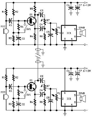
The intercom schematic provides a reliable communication line and is straightforward to construct. The circuit consists of an amplifier, two switches, and two loudspeakers. If additional stations (speakers) are desired, more switches can be incorporated into the circuit. The...
Nowadays, many intercom units are equipped with video cameras, allowing users to see as well as hear who is at the door. Unfortunately, the camera lens is... Intercom systems with integrated video capabilities enhance security and convenience by enabling visual...
The Link circuitry is simple and efficient, employing just two ICs, half a dozen transistors, and a handful of garden variety components. It all runs on 12 volts and is easily assembled. You can have your own home intercom...
DIY Intercom Circuit Full-duplex intercom circuit schematic, cable on the way to the intercom circuit. The DIY intercom circuit is designed to facilitate two-way communication using a full-duplex system. This allows simultaneous transmission and reception of audio signals, enabling clear...
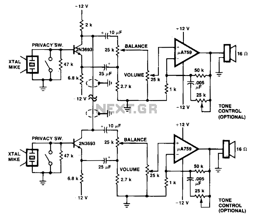
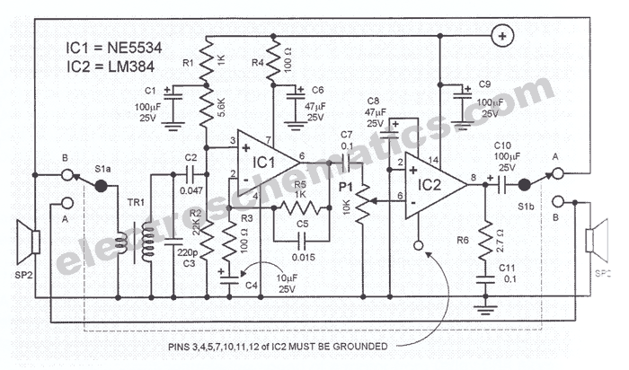
This system utilizes p.A759 audio IC devices and a shared connection between the preamplifiers as an interconnect. Either microphone can drive either speaker. Duplex operation is achievable with a single cable consisting of two wires. The system design incorporates the...
A project is proposed to construct a two-phone intercom system capable of functioning over a distance of up to 1 kilometer. The system will utilize the speaker of each phone to produce a ringing sound on the other end. The...