
Intercom Circuit
The intercom circuit is designed to facilitate clear communication in various environments, such as homes or offices. The use of the LM382 integrated circuit as the final amplifier is crucial for achieving the desired audio output level, allowing for effective communication over a range of distances. The preset amplification level of 50 ensures that the audio signal is adequately boosted for clarity, making it suitable for intercom applications.
The inclusion of an operational amplifier (IC2) with an amplification factor of 11 further enhances the input signal before it reaches the LM382, ensuring that even quieter sounds are effectively amplified. The frequency response of 160 Hz to 10 kHz is tailored for voice communication, as it covers the essential frequency range for human speech while filtering out unnecessary high-frequency noise that could detract from the clarity of the conversation.
To ensure optimal performance, it is recommended to use speakers that can also act as microphones, as this dual functionality enhances the intercom's effectiveness. The enclosure of the intercom circuit is also a critical design consideration; it should be constructed in a manner that minimizes acoustic feedback and maximizes microphone sensitivity.
The use of transformer TR1 as an impedance converter is a vital aspect of the circuit design. By stepping down the voltage from 220V to 6V, the transformer not only provides the necessary power supply for the circuit but also raises the speaker's impedance to approximately 10 kΩ. This adjustment is essential for maintaining audio quality and preventing distortion, which can occur when connecting low-impedance speakers directly to the amplifier.
Lastly, the separation of the power supply unit from the main circuit is an important design practice that helps to mitigate electromagnetic interference, ensuring that the audio signal remains clear and free from noise. Capacitor C1 plays a significant role in this regard, as it effectively suppresses high-frequency interference that may otherwise compromise audio quality. With a current consumption of about 210 mA and an output power of 1.8 watts, this intercom circuit is both efficient and effective for its intended purpose.The intercom schematic fulfills its tasks to provide a reliable communication line and is very simple to construct. The circuit is made up of an amplifier, two switches and two loudspeakers. If additional stations (speakers) are wished, additional switches are just incorporated into the circuit.
IC LM382 is used as the final amplifier. It delivers nearly 2 watts of audio power by 15 volts supply voltage. Amplification is preset to 50. C9 serves as supply bypass. Another IC is used to boost the input signal before it is passed into the LM384. IC2 is an op-amp with an amplification factor of 11. The frequency bandwith is 160 Hz to 10 kHz. These values were chosen since the device is to be used only as intercom and not as HIFI amplifier. To achieve the best performance, use speakers that can also function as microphones. The intercom must be constructed inside a box so that the microphone function is optinum. Since the impedance of most speakers are quite low, an impedance converter is needed to maintain a good audio quality. This is done by the transformer TR1. TR1 is a normal 220/6V step-down transformer. The 6V winding of the transformer is connected to the speaker and raises its impedance to about 10 kohms.
In constructing the intercom circuit, house the power supply unit separately from the main circuit to avoid interference. C1 suppresses HF interference. The current consumption is about 210 mA with 1. 8 watt output. 🔗 External reference
Related Circuits
This is an electric thermometer circuit composed of the LM134. In the circuit, the voltage or current output by the LM134 is proportional to the thermodynamic temperature, which can be read on a 100 µA meter. The test temperature...
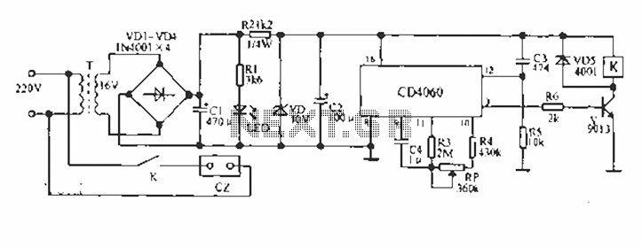
A CD4060 production time controller circuit is illustrated below. It is connected in such a way that R5 and C3 form a differential circuit to create a delay time from the start. Under the influence of the oscillating signal,...
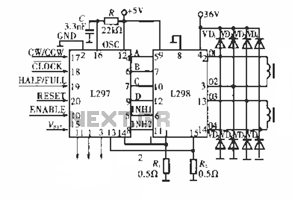
The circuit operates using a dedicated stepping motor controller, the L297. Pin 17 (CW/CCW) is utilized to control the rotation direction of the stepper motor. Pin 18 (CLOCK) regulates the speed of the stepper motor, while pin 19 (HALF/FULL)...
This is a follow-up to an earlier post regarding a specific circuit schematic. The circuit is designed to operate at a supply voltage of 5V, and testing has confirmed that the original device functions correctly at this voltage. A...
The gain adjustment circuit for the ISO103 is illustrated. The circuit features a gain trimming potentiometer, R2, which serves to enhance the gain accuracy and offset of the ISO103, thereby allowing for external adjustments. R2 provides a gain trim...
To enhance usability during nighttime, the receiver features a scale with bias lighting, and the surface behind the scale is coated with a fluorescent material. To activate the scale illumination, press button 3. Radio programs can be listened to...