
Double IC For Circuit an Infrared Toy Car Motor Controller

The Infrared Toy Car Motor Controller circuit utilizes the 4047 and 4017 ICs to manage the operation of the toy car motors effectively. The 4047 is configured in astable mode to generate a square wave output, which serves as a clock signal for the 4017 decade counter. The 4017 is responsible for sequentially activating the outputs that control the motors, allowing for forward and reverse motion as well as turning.
The circuit features a 16V capacitor that provides stability and filtering for the power supply, ensuring that the ICs operate reliably. A 100k resistor is incorporated in the timing circuit of the 4047 to set the frequency of the output signal. The use of dual ICs enhances the functionality of the circuit, allowing for more complex control over the motors.
Additional components include diodes that protect the circuit from back EMF generated by the motors, LEDs that provide visual feedback on the circuit's operation, and transistors that amplify the control signals to drive the motors effectively. The switch allows the user to turn the circuit on and off, providing simple user interaction.
Overall, this circuit design demonstrates a practical application of basic electronics principles, integrating various components to create a functional motor controller for an infrared toy car. The combination of the 4047 and 4017 ICs, along with the supporting components, results in a robust solution for controlling motor functions in toy applications.The following circuit shows about Circuit an Infrared Toy Car Motor Controller. This circuit based on the 4047 and4017 IC. Features: 16V Capacitor, 100k Resistor, Double IC. Component: IC, Switch, Diode, LED, Resistor, Capacitor, Motor, Transistor. [diychamber. com] Tags: Capacitor, circuit diagram, control circuit, control diagram, co ntrol schematic, Diode, electronic circuit, electronic control, IC, LED, Motor, Resistor, schematic diagram, switch, Transistor 🔗 External reference
Related Circuits
The goal is to transmit more information by carrying articles. Please send an email to [email protected] within 15 days if there are issues related to article content, copyright, or other concerns. The content will be deleted promptly. In the context...
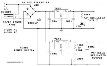
The circuit utilizes the 7805 voltage regulator, which features three connections: input, output, and ground. It delivers a fixed output voltage, with the last two digits of the part number indicating the specific output voltage, such as 05, 06,...
This circuit is designed to operate an electric strike or an electromagnetic lock on a door. It does not control the door's opening or closing but rather activates a small electromagnetic strike that unlocks the door. The opener features...
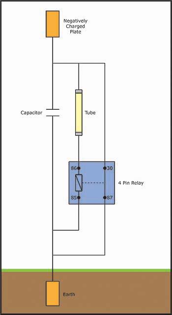
An individual has been studying Nikola Tesla's work for approximately 11 months and recently discovered Imhotep's concept of Radiant energy. The study of Nikola Tesla's contributions to electrical engineering and energy transmission has led to significant advancements in understanding electromagnetic...
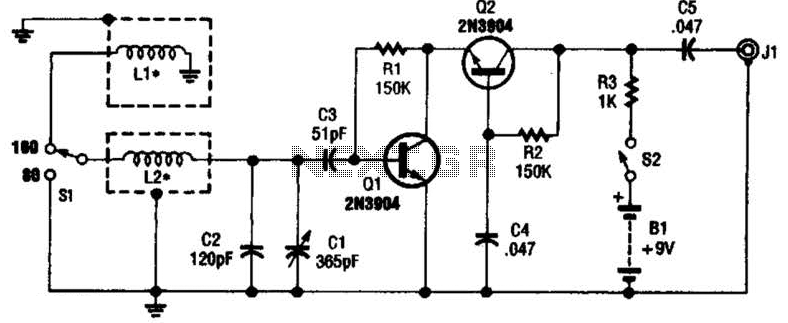
This antenna may assist in minimizing power-line noise. It consists of a plastic hula hoop or conduit with a diameter of 3 feet, which is covered with aluminum foil to serve as a shield for LI and L2. LI...
This circuit is designed to indicate when a plant requires watering. An LED flashes at a low frequency when the soil in the flower pot is excessively dry, and it turns off as the moisture level rises. The sensitivity...