
hobby power supply circuit
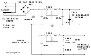
The 7805 voltage regulator is a linear voltage regulator widely used in electronic circuits to provide a stable output voltage. It is part of the 7800 series of voltage regulators, which are known for their reliability and ease of use. The device operates by taking a higher input voltage and converting it to a lower, regulated output voltage. The three terminals of the 7805 are configured as follows: the input pin receives the unregulated voltage, the output pin delivers the regulated voltage, and the ground pin serves as a reference point for the circuit.
The output voltage of the 7805 is fixed at 5V, making it suitable for powering microcontrollers, sensors, and other low-voltage devices. The regulator can handle input voltages up to 35V, providing a significant voltage drop across the device while maintaining a stable output. Its maximum output current rating is 1 amp, which is adequate for many applications. However, it is essential to ensure that the load does not exceed this current limit to prevent overheating and potential damage to the regulator.
Thermal management is crucial when using the 7805. The built-in thermal shutdown feature protects the device from overheating by shutting it down if the junction temperature exceeds safe limits. To enhance heat dissipation, it is advisable to attach a heatsink to the regulator, especially in applications where it may be subjected to high load currents or elevated ambient temperatures. Proper layout and design considerations, such as ensuring adequate airflow and using appropriate trace widths on printed circuit boards, will further aid in maintaining optimal operating conditions.
In summary, the 7805 voltage regulator is a versatile component that provides a reliable means of regulating voltage in electronic circuits. Its simple design, coupled with built-in protection features, makes it a preferred choice for many engineers and hobbyists alike.The circuit is based around the 7805 voltage regulator. It has only 3 connections (input, output and ground) and it provides a fixed output. The last two digits of the part number specify the output voltage, eg. 05, 06, 08, 10, 12, 15, 18, or 24. The 7800 series provides up to 1 amp load current and has on-chip circuitry to shut down the regulator (rather than blowing out) if any attempt is made to operate it outside its safe operating area. (If this happens to you, let the chip cool down & attach the heatsink. ) 🔗 External reference
Related Circuits
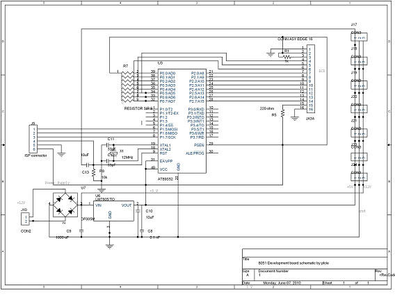
DTMF-based Robo Car design using the 8051 microcontroller project. This project demonstrates a method to control a domestic system using the DTMF tone generated by a telephone instrument when the user presses the keypad buttons of a mobile phone...
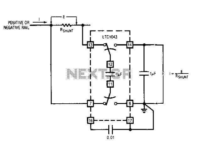
This capability has wide application in battery and solar-powered systems. If the ground-referred voltage output is unloaded by an amplifier, the shunt can operate with very little voltage drop across it, minimizing losses. The LTC1043 can sense current through...
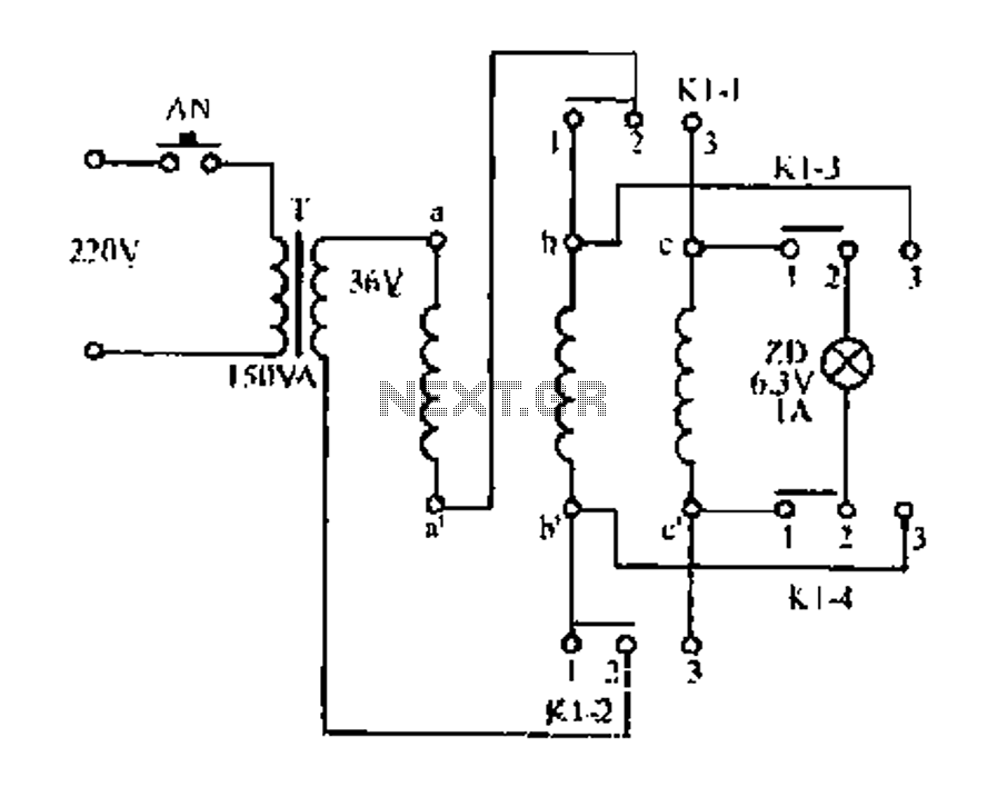
Figure aa, bb, and ce represent three-phase windings. A double throw switch Kl-1 to Kl-4 is positioned on the left side, connecting phases 1 and 2. At this point, aa and bb are in series with the secondary of...

This circuit design for an amplifier was created to address the gap in the 3-10 Watts power output range of audio amplifiers available in RED Free Circuit Designs. A straightforward, low-component-count amplifier was developed based on the successful 45...
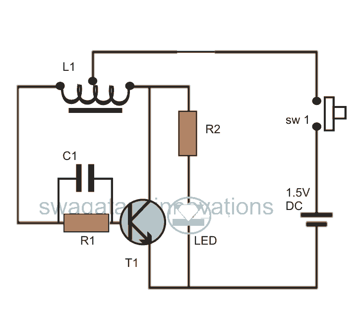
This post discusses blue and white LED drivers utilizing a joule thief circuit. Further exploration of the circuit's functionality is provided, along with simulation points. The joule thief circuit is a simple and efficient boost converter that allows for the...
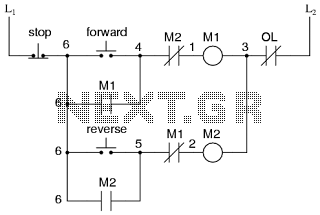
This is the power diagram for motor forward and reverse operation. To change the motor direction, one polarity must be altered, for example, changing R to S. For detailed information, please refer to the following. The described power diagram illustrates...
Warning: include(partials/cookie-banner.php): Failed to open stream: Permission denied in /var/www/html/nextgr/view-circuit.php on line 713
Warning: include(): Failed opening 'partials/cookie-banner.php' for inclusion (include_path='.:/usr/share/php') in /var/www/html/nextgr/view-circuit.php on line 713