
Dry Cell Charger
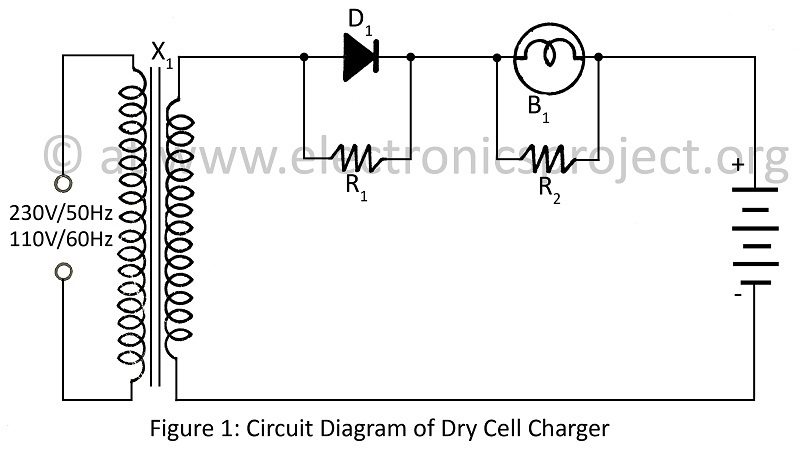
The dry cell charger operates on the principle of Periodic Current Reversal (PCR), which enhances the efficiency of the charging process by periodically reversing the current direction. This method helps in reducing the buildup of gas bubbles on the electrode surfaces, which can hinder the charging process and prolong the lifespan of the dry cell.
The circuit typically consists of a few key components: a power supply, a switching mechanism, and a control circuit. The power supply provides the necessary voltage and current for charging the dry cell. The switching mechanism, often implemented using transistors or relays, alternates the current flow direction at predetermined intervals. The control circuit may include a timer or microcontroller to manage the switching frequency and duration, ensuring optimal charging conditions.
The schematic diagram for this charger would include the power supply connected to the input of the switching mechanism. The output of the switching mechanism would be linked to the terminals of the dry cell. Additional components such as resistors, capacitors, and diodes may be included to stabilize the circuit and protect against voltage spikes.
This design is particularly advantageous for applications where a reliable and efficient charging method is required without the complexity of larger, more intricate circuits. The use of fewer components not only simplifies the construction but also reduces the overall cost, making it an attractive solution for various DIY projects and practical applications in battery management.Dry Cell Charger utilizing very few component for recharging dry cell 6 to 8 time using principle PCR (Periodic Current Reversal) circuit diagram of various project. 🔗 External reference
Related Circuits
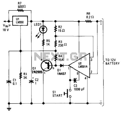
This high-performance charger efficiently charges gelled lead-acid batteries and automatically shuts off upon reaching a full charge. Initially, the charging current is maintained at 2 A; however, as the battery voltage increases, the current gradually decreases. Once the current...
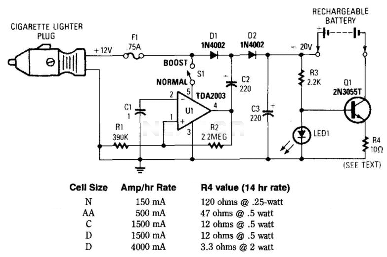
This circuit provides an output of up to 20 V from a 12-V automotive supply, enabling constant current charging of NiCad battery assemblies with a total voltage of approximately 18 V. The circuit utilizes a square-wave oscillator (VI) and...
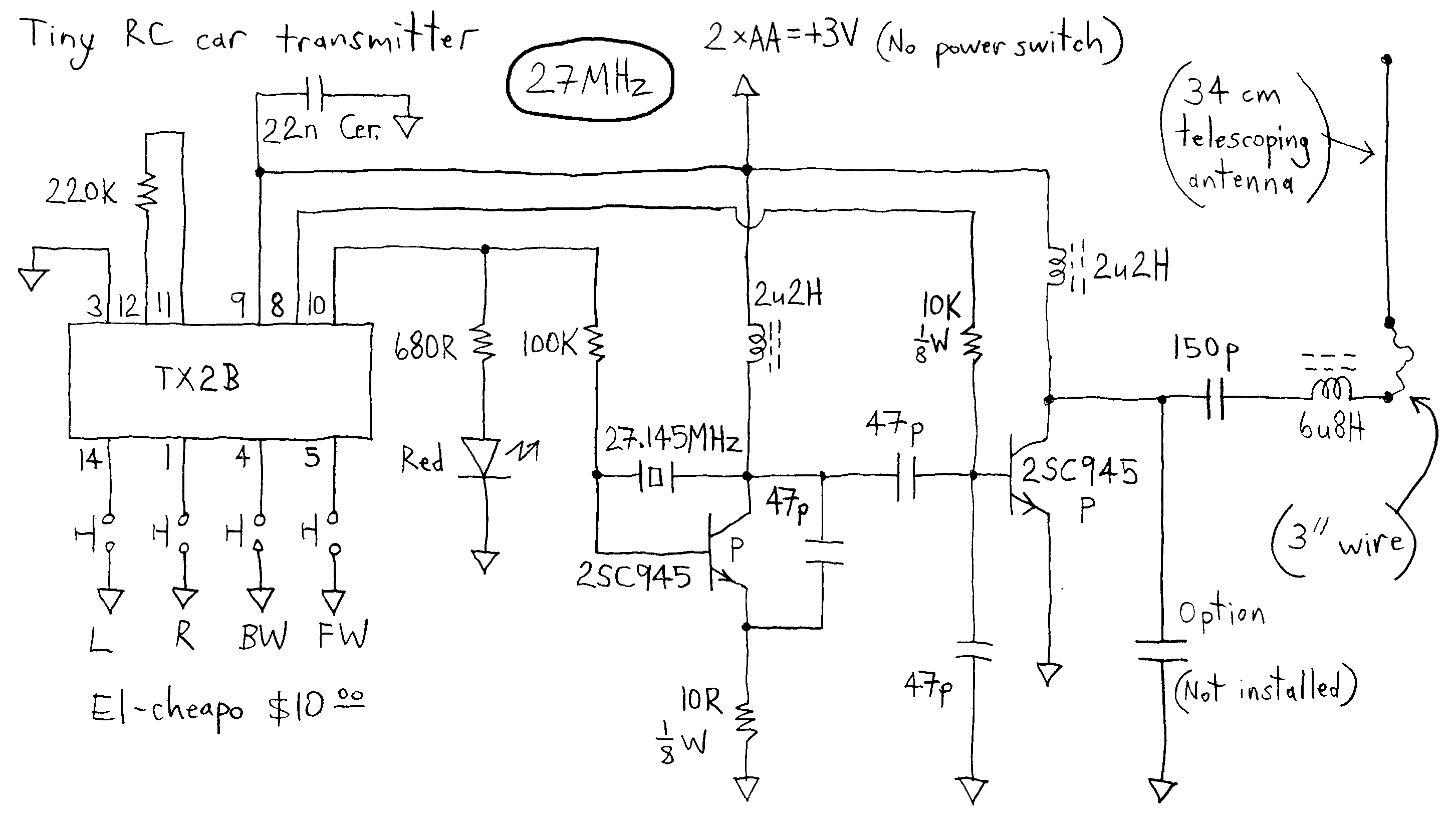
The transmitter runs on only 3V whereas most others run on more voltage. This dirt cheap item uses non-adjustable inductors so it is not possible to tweak for higher output. The common TX2B chip is manufactured by HIGHLAND (SHENZHEN)...
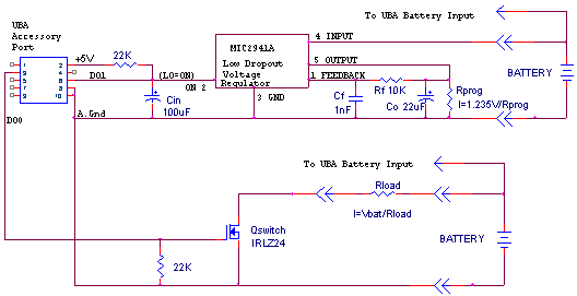
The UBA is limited to discharging up to 2.5A per channel. This discharge rate is adequate for testing 99% of the batteries on the market. However, it is insufficient for properly testing batteries that are rapidly discharged in normal...
Most Bulle clocks require their magnets to be rejuvenated before they can operate correctly with a standard 1.5V cell. The first significant magnet material was cobalt-chrome steel, introduced in 1921. Prior to this, carbon steel was hardened through heating...
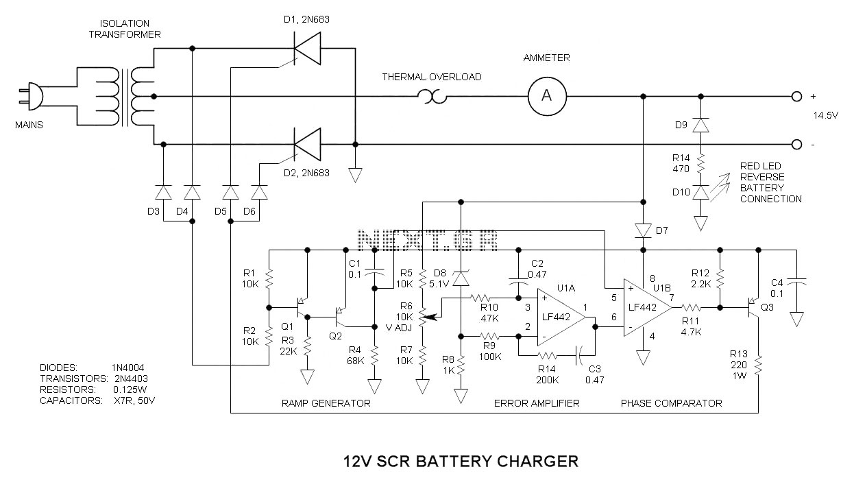
This 12V SCR battery charger circuit is unique in several aspects, which contribute to its complexity. The 12V SCR (Silicon Controlled Rectifier) battery charger circuit is designed to efficiently charge lead-acid batteries while providing a reliable and stable charging process....