
Tiny RC Cars - Transmitter and Charger
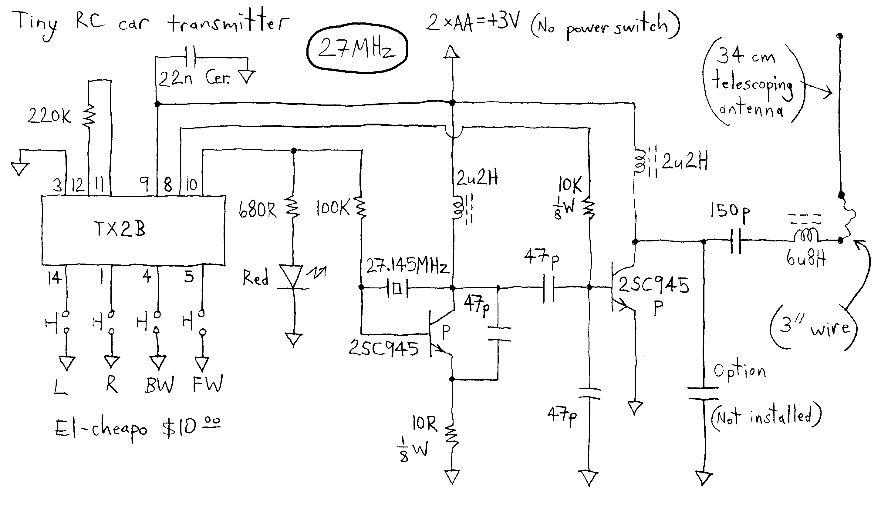
The described transmitter circuit operates at a low voltage of 3V, which is notably lower than many comparable devices that require higher voltage levels for operation. This characteristic makes the transmitter an economical option for various applications. The use of non-adjustable inductors indicates a fixed design, which limits the ability to modify the output frequency or power levels. This can be a significant consideration for users needing flexibility in their RF designs.
The TX2B chip, a common component in this circuit, is produced by HIGHLAND (SHENZHEN) ELECTRONICS CO LTD and REALTEK SEMICONDUCTOR CORP, among others. This chip is typically used in low-power RF transmitter applications, making it suitable for short-range communication systems such as remote controls, wireless microphones, and other similar devices.
The circuit operates at two specified frequencies, 27 MHz and 49 MHz. These frequency bands are often utilized for various consumer electronics and can be subject to regulations regarding transmission power and range. The design of the circuit likely includes essential components such as capacitors, resistors, and possibly a crystal oscillator to stabilize the frequency output.
For practical implementation, the layout should ensure minimal interference and optimal performance. Proper grounding and shielding techniques should be employed to mitigate noise and enhance signal integrity. The circuit may also include a simple antenna design, which is crucial for effective transmission and reception of the RF signals.
Datasheets for the TX2B chip and other components may be available online, providing detailed specifications, pin configurations, and suggested application circuits, which can be instrumental for engineers looking to implement or modify this transmitter circuit for specific use cases.The transmitter runs on only 3V whereas most others run on more voltage. This dirt cheap item uses non-adjustable inductors so it is not possible to tweak for higher output. The common TX2B chip is manufactured by HIGHLAND (SHENZHEN) ELECTRONICS CO LTD and by REALTEK SEMICONDUCTOR CORP and others. Datasheets are available on the web but I don`t remember where now. Here is the circuit at 27 and 49 MHz: 🔗 External reference
Related Circuits
This simple transmitter operates from a 9V battery as shown above. It was built to address the challenges faced by a singing group using FM microphones in a church setting. The choir performs in an a cappella style, and...
This article describes a circuit for a simple single-cell lithium-ion battery charger utilizing the LP2391 regulator IC. The circuit presented is designed for charging a single-cell lithium-ion battery efficiently. The LP2391 is a linear voltage regulator that provides a constant...
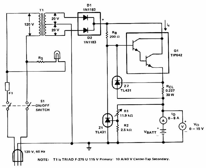
Lead Acid Battery Charger with current limit power supply. Refer to the specified page for an explanation of the related circuit diagram. The lead-acid battery charger with a current limit power supply is designed to safely charge lead-acid batteries while...
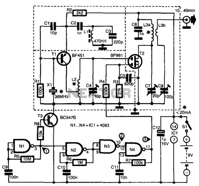
The transmitter is specifically designed for radio amateurs to function as a radio beacon, delivering a high-quality signal devoid of unwanted harmonics. Transistor T1, in conjunction with crystal X1, serves as a 36-MHz oscillator. Filter L1/C3 prevents the circuit...
This PLL transmitter is digitally programmable, ensuring stable frequency operation. It operates within the 88-108 MHz range with an output power of up to 500 mW. With minor modifications, the frequency can be adjusted to 50-150 MHz, and the...
The following diagram represents the schematic of a Ni-CAD battery charger circuit, which features current and voltage limiting to prolong the battery's lifespan. The lamp L1 will illuminate brightly while the LED will be off when the battery is...