
Dual Relay Driver Board Circuit Schematic

The relay driver circuit utilizes a BC547 NPN transistor, which acts as a key component in controlling the relay's operation. The common-emitter configuration of transistors Q1 and Q2 allows for significant amplification of the input signal, which is crucial for driving the relay coil effectively. The 100-fold increase in current gain means that a small input current can activate the relay, making the circuit highly efficient.
Resistors R3 and R4 play an essential role in protecting the transistors from excessive current, which could lead to damage or malfunction. By limiting the input current, these resistors ensure that the transistors operate within their safe limits, enhancing the reliability of the circuit.
Diodes D3 and D4 are critical for managing inductive kickback generated when the relay coil is de-energized. This kickback can produce high-voltage spikes that may damage the transistors or other components in the circuit. The diodes effectively clamp these voltage spikes, allowing for smoother operation and preventing potential damage.
Overall, this relay driver circuit design is a robust solution for controlling various types of relays, providing both efficiency and protection for the components involved. The careful selection of components and their configuration ensures a reliable performance in various applications where relay control is required.This relay driver boosts the input impedance with a regular BC547 NPN transistor (or equivalent). Very common driver. It can drive a variety of relays, including a reed-relay. Transistor Q1and Q2 are a simple common-emitter amplifier that increases the effective sensitivity of the 12 volt relay coil about a 100 times, or in other words, the current gain for this circuit is 100. Using this setup reduces the relay sensitivity to a few volts. R3 and R4 restricts the input current to Q1 and Q2 to a safe limit. Diodes D3 and D4 are EMF dampers and filter off any sparking when the relay 🔗 External reference
Related Circuits
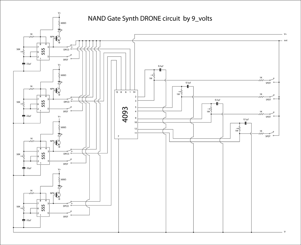
This is a brief jam session to explore the capabilities of a recently completed step sequencer. This device is quite enjoyable and expands creative possibilities. A detailed post with the circuit and instructions for building it will be provided...
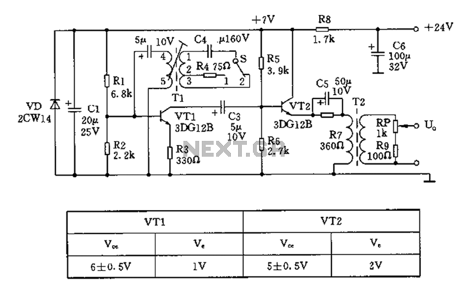
The 450/800Hz oscillation circuit depicted in the figure utilizes transformer coupling. The frequency conversion is achieved by varying the inductance through a variable filter tap (T1). When the switch control signal (S) is set to position 1, the oscillator...
In the silicon-controlled trigger circuit, a cadmium sulfide cell is connected to a relaxation oscillator, which serves as a sensor to activate a blinking light in a darkroom. This setup causes a speaker to emit a warning sound of...
A new member has joined the forum and is seeking assistance with electronics, particularly from a technical engineering perspective, although they have some experience with circuits and schematics. The individual is likely looking to enhance their understanding of electronic components,...
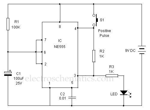
This 555 timer is designed uniquely to provide a positive output through control over its reset pin. Typically, the 555 timer IC is triggered by applying a negative voltage. The 555 timer is a versatile integrated circuit widely used in...
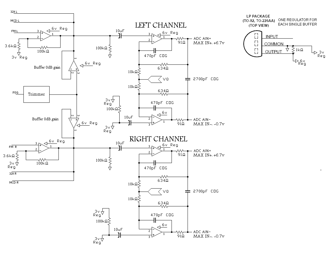
A program is needed to set the channels to their maximum level or to write the full scale to the Digital-to-Analog Converter (DAC). The MD schematics indicate that the audio signals are mixed with ratios of 0.0431 for the...