
450 800Hz signal generator circuit diagram
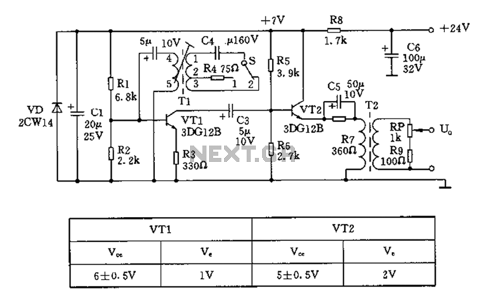
The described 450/800Hz oscillation circuit is a versatile electronic oscillator that employs a transformer coupling method to achieve frequency conversion. The circuit operates by utilizing a variable filter tap (T1) which allows for the adjustment of inductance, thus enabling the selection of different oscillation frequencies.
In position 1 of the switch control signal (S), the oscillator circuit is configured with capacitors C4 and T1, producing an output frequency of 800Hz. The output signal is derived from the emitter of the transistor VT2, which acts as an amplifier in the circuit. The output level can be adjusted using the potentiometer (RP), allowing for fine control over the amplitude of the 800Hz signal. The resistor R4 serves a crucial role in regulating the oscillation amplitude, ensuring that the output remains stable and within desired parameters.
When the switch is toggled to position 2, the oscillation frequency changes to 450Hz. This is achieved through the interaction of capacitors C1-3 and T1, which together determine the new frequency. The T1 component is equipped with a threaded adjustment lever, providing a means for precise frequency tuning. This feature is particularly beneficial for applications requiring exact frequency specifications.
Overall, the 450/800Hz oscillation circuit is designed for flexibility and precision, making it suitable for various electronic applications where specific frequency outputs are necessary. The use of transformer coupling enhances the circuit's performance by allowing for efficient signal transfer and amplification.450/800Hz oscillation circuit shown in FIG oscillator is a transformer coupling. The frequency conversion is made different inductance is achieved by changing the oscillation t ank variable filter tap Tl. Pull the switch control signal S to 1 block, l-2 oscillator circuit C4 and Tl end and then a frequency of 800Hz, by VT2 emitter output to RP potentiometer adjustable arm output. By adjusting potentiometer RP can change the 800Hz output size. Oscillation circuit resistor R4 for adjusting 800Hz oscillation amplitude. S to pull the 2 block, C 1-3 and T1 phase, the oscillation frequency is 450Hz. T1 threaded adjustment lever to adjust trimming oscillation frequency.
Related Circuits
This RS232 power supply circuit diagram is a simple RS-232 line driver power supply that operates from an input voltage as low as 4.2V and delivers an output of ±12V at ±40 mA with an efficiency of better than...

The circuit utilizes a 555 timer IC to create a lighting group delay effect, as illustrated in Figure 2-46. It consists of the 555 IC along with a resistor and capacitor configuration that establishes the delay. The circuit remains...
This circuit combines the advantages of low input offset voltage and drift without compromising the overall dynamic performance of the system. When compared to a standalone FET input operational amplifier, the composite amplifier circuit demonstrates a 20-fold improvement in...
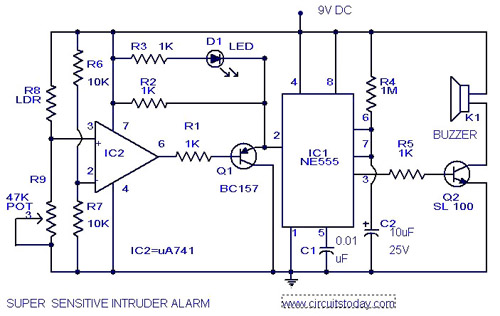
The circuit diagram represents an ultra-sensitive intruder alarm. A shadow from an intruder passing nearby is sufficient to trigger the alarm. The operational amplifier IC2 (uA 741) is configured as a sensitive comparator, with its set point determined by...
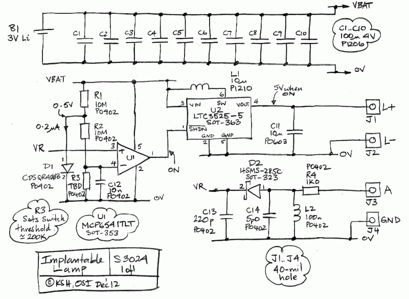
The Implantable Lamp (A3024) is a radio-controlled lamp powered by a battery. Once encapsulated in epoxy and silicone, it is waterproof and compact, allowing it to be implanted in an animal. The A3024 can theoretically be activated by any...
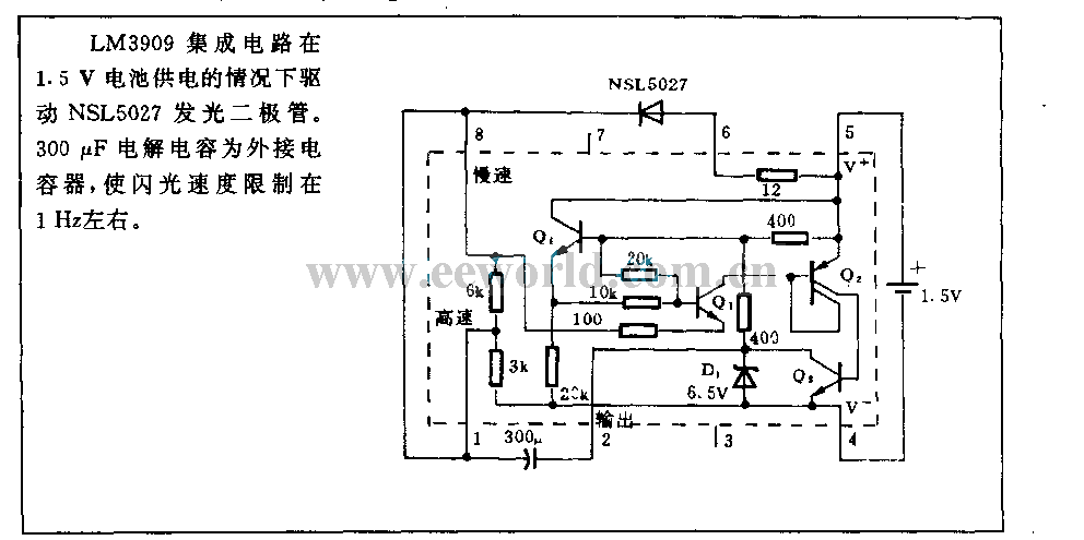
With a 1.5V battery supply, the integrated circuit LM3909 can drive the light-emitting diode NSL5027. The 300μF electrolytic capacitor acts as a timing capacitor, which limits the flash speed to approximately 1Hz. The circuit utilizes the LM3909, a popular LED...
Warning: include(partials/cookie-banner.php): Failed to open stream: Permission denied in /var/www/html/nextgr/view-circuit.php on line 713
Warning: include(): Failed opening 'partials/cookie-banner.php' for inclusion (include_path='.:/usr/share/php') in /var/www/html/nextgr/view-circuit.php on line 713