
Dynamic Microphone Amplifier
The following circuit is a dynamic microphone compressor circuit that is simple yet yields satisfactory results, producing outstanding audio output. The circuit operates on a fundamental principle where the first transistor functions as a microphone preamplifier, the second transistor acts as a buffer, and the third transistor is incorporated into a feedback circuit.
This setup is part of a two-station intercom system that utilizes two wires to connect each intercom unit. Each unit is self-contained, featuring its own battery, speaker, microphone, and amplifier circuit. An LM386 audio power amplifier is employed, which is widely available, requires minimal external components, and is well-suited for battery operation.
Additionally, a six LED stereo VU display diagram is constructed using the Dot/Bar Display Driver IC LM3915. This VU display should be connected before the amplifier module circuit, and it can be integrated at the preamplifier output, tone control input/output, or equalizer input/output.
The LM3915 is a monolithic integrated circuit designed to sense analog voltage. The microphone amplifier circuit is intended for use with low impedance microphones (approximately 200 ohms). It operates effectively with stabilized voltages ranging from 6 to 30 VDC. If the impedance adapter part with T1 is not built, the circuit will serve as a microphone amplifier for higher impedance microphones, in which case the signal should be directly connected to C7.
A component list includes R1 = 15 kΩ, C1 = unspecified. Furthermore, there is a diagram for a 5-band graphic equalizer circuit based on operational amplifiers. The NE5532 or LM833 is recommended as a low-cost op-amp chip that provides fairly good quality output. Each integrated circuit contains dual op-amps, necessitating four NE5532 or LM833 ICs to construct the 5-band equalizer circuit.Dynamic microphones are versatile and ideal for general-purpose use. They use a simple design with few moving parts. They are relatively sturdy and resilient to rough handling. They are also better suited to handling high volume levels, such as from certain musical instruments or amplifiers. They have no internal amplifier and do not require batte ries or external power. - For the best performance, use metal film resistor, MKM type for unpolar capacitor and tantalum type for bipolar capacitor. Use stabled and regulated power supply. With a 3mVpp input signal the output will be 800mVpp. The maximum output voltage was 10Vpp when the input is 50mVpp. The frequencies domain is between 50Hz and 100KHz. Tags: amplifier, amplifier circuit, Dynamic Microphone, dynamic microphone amplifier, Dynamic microphone diagram, mic amplifier, microphone amplifier, microphone amplifier circuit, The circuit below is a Dynamic Mic Compressor circuit is simple but the results are quite satisfactory.
Audio output sounded outstanding. The principle of this circuit is very simple, the first transistor is used as Mic Pre-Amp. Then a second transistor used as a buffer. And the third transistor is a feedback circuit. Supply voltage. This a two station intercom. It uses two wires to run between each intercom unit. Each is self contained with its own battery, speaker, microphone and amplifier circuit. An LM386 audio power amplifier is used. It is widely available, used a minimum of external parts and is well suited to battery operation. It will give. The following circuit is six LED stereo VU display diagram which build using Dot/Bar Display Driver IC LM3915. This VU disply should be connected before amplifier module circuit. You may connect this circuit at pre-amp output, tone control input/output or equaliser input/output. About LM3915: The LM3915 is a monolithic integrated circuit that senses analog voltage. This circuit is a microphone amplifier for use with low impedance (~200 ohm) microphones. It will work with stabilized voltages between 6-30VDC. If you don`t build the impedance adapter part with T1, you get a mic-amp for higher impedance microphones.
In this case, you should directly connect the signal to C7. Component list: R1=15k C1=. This is the diagram of 5 band graphic equaliser circuit. The circuit is based on operational amplifier, the NE5532 or LM833 is the right choice for low cost op-amp chip with fairly good quality output. Each IC contains dual op-amps circuit, so you will need 4 ICs of NE5532 or LM833 to build this 5. 🔗 External reference
Related Circuits
This circuit turns off an amplifier or any other device when a low-level audio signal fed to its input is absent for at least 15 minutes. Pressing P1 switches the device on, supplying power to any appliance connected to...
A straightforward 4-channel video amplifier electronic circuit can be constructed using the NJM2582 integrated circuit, which is suitable for video applications with a SCART connector. The design of this circuit is uncomplicated and requires only a few external electronic...
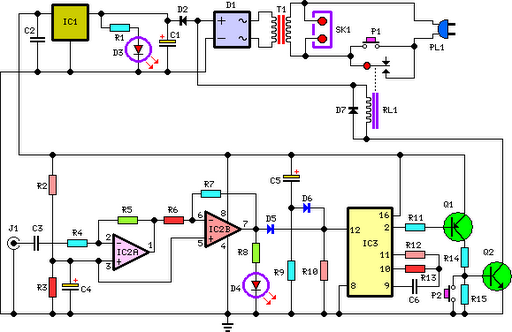
This circuit deactivates an amplifier or any connected device when a low-level audio signal at its input is absent for at least 15 minutes. Pressing P1 turns the device on, supplying power to any appliance connected to SK1. The...
The addition and subtraction functions of an operational amplifier are facilitated through an external feedback network, which places the integrated operational amplifier in a deep state of negative feedback. In this linear region, the relationship between input and output...
The main features of the MULTIWATT Package, a trademark of SGS-THOMSON Microelectronics, include a power amplifier IC designed specifically for car radio applications. It offers a high current capability of 3.5A and can drive a very low impedance of...
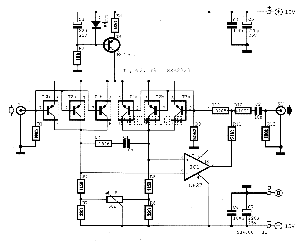
The preamplifier is designed for signal sources such as low-impedance moving coil cartridges (MC) used in high-fidelity turntables. The amplifier has an impedance of 100 ohms. To maintain low noise levels, three double-type transistors, either MAT03 or SSM2220, are...