
Amplifier Timer Circuit Schematic
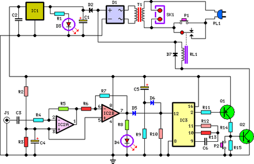
The circuit operates on the principle of signal detection and timing, utilizing an audio input to control a relay that manages power to connected devices. The initial stage involves the amplification and squaring of the audio signal through operational amplifiers IC2A and IC2B, which enhances the signal to a level suitable for monitoring. LED D4 serves as a visual indicator of the audio signal's presence, illuminating briefly when the signal is detected.
The timing function is managed by IC3, which is configured to count the absence of the audio signal. Capacitor C3 plays a crucial role in resetting this timing mechanism. When the audio signal is present, C3 is charged, preventing IC3 from reaching its threshold. However, if the audio signal is absent for the specified duration, IC3 triggers a change in its output state at pin 2, transitioning from low to high. This transition turns off the transistors Q1 and Q2, which are responsible for driving the relay. The relay's deactivation results in the disconnection of power to SK1, effectively shutting down the connected devices.
The circuit includes provisions for immediate manual control through switch P2, allowing for the quick deactivation of the system regardless of the audio signal state. Additionally, the reset mechanism provided by C5 and R9 ensures that IC3 is properly initialized upon power-up, establishing a reliable starting condition for the timing operation. This design is particularly useful in applications requiring automatic power management based on audio signal presence, ensuring energy efficiency and equipment protection.This circuit turns-off an amplifier or any other device when a low level audio signal fed to its input is absent for 15 minutes at least. Pushing P1 the device is switched-on feeding any appliance connected to SK1. Input audio signal is boosted and squared by IC2A & IC2B and monitored by LED D4. When D4 illuminates, albeit for a very short peak, I C3 is reset and restarts its counting. Pin 2 of IC3 remains in the low state, the two transistors are on and the relay operates. When, after a 15 minutes delay, no signal appeared at the input, IC3 ends its counting and pin 2 goes high. Q1 & Q2 stop conducting and the relay switches-off. The device is thus completely off as also are the appliances connected to SK1. C5 & R9 reset IC3 at power-on. P2 allows switch-off at any moment. 🔗 External reference
Related Circuits
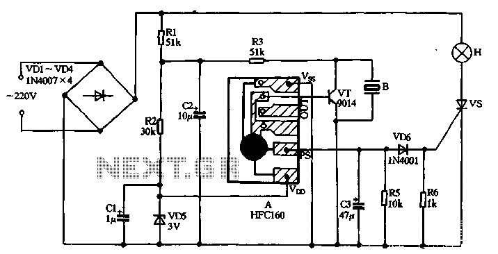
220V AC power is supplied through a VD1 to VD4 bridge rectifier and a voltage regulator circuit involving R1, R2, and VD5 components. The output provides a DC voltage of approximately 3V, which powers the manifold A. The manifold...
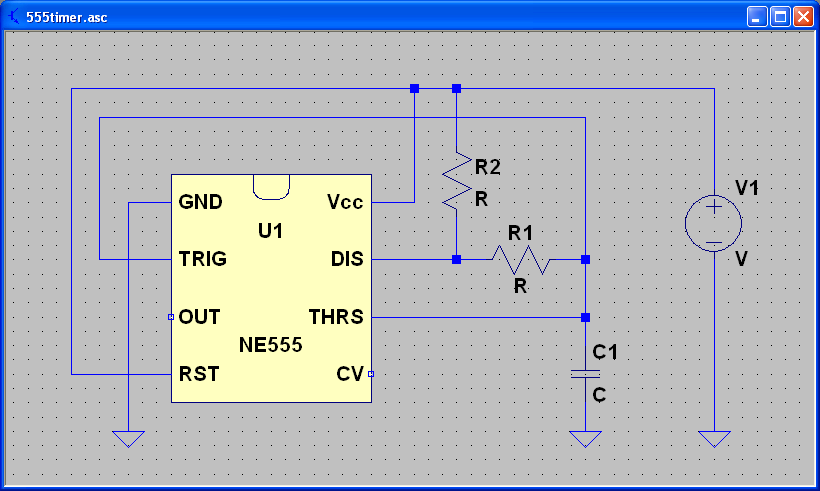
ECEN 2250 myDAQ Experiment Capacitors and the 555 Timer. The experiment involving capacitors and the 555 timer within the ECEN 2250 myDAQ framework focuses on understanding the behavior of capacitors in electronic circuits and the functionality of the 555 timer...
Charging a mobile phone or cellphone battery presents a significant challenge while traveling, as a power supply source is often not readily available. If the cellphone remains switched on continuously, its battery can deplete within five to six hours,...
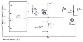
The values of the LM56 thermostat project circuit diagram for resistors R1, R2, and R3 at the travel points VT1 and VT2 can be determined using the following equations. This electronic circuit thermostat with the IC LM56 serves as...
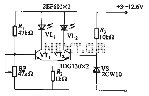
When the battery voltage is within the range of 7 to 12.6V, the light-emitting diode VLi illuminates, maintaining a consistent brightness. If the battery voltage drops below 7V, VLi begins to emit a red light, and the brightness of...
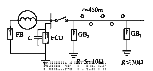
Direct distribution lightning generator with a capacity range of 300 to 1500 kW, designed for single-phase applications. The generator facilitates the direct distribution of electrical energy, providing reliable performance for various applications. The lightning generator operates within a specified power...
Warning: include(partials/cookie-banner.php): Failed to open stream: Permission denied in /var/www/html/nextgr/view-circuit.php on line 713
Warning: include(): Failed opening 'partials/cookie-banner.php' for inclusion (include_path='.:/usr/share/php') in /var/www/html/nextgr/view-circuit.php on line 713