
Ears and Speakers Protector

Amplifiers are crucial components in audio systems, responsible for boosting audio signals to drive loudspeakers. However, when the output volume exceeds safe levels, it can result in auditory discomfort and physical damage to speakers. To mitigate these risks, it is essential to implement a volume control mechanism within the amplifier circuit.
A basic approach to controlling the output volume involves the integration of a potentiometer or digital volume control circuit. The potentiometer can be placed in the signal path, allowing users to adjust the resistance and, consequently, the signal level reaching the amplifier output. This simple method provides an intuitive interface for users to manage volume levels.
For more advanced applications, a digital volume control circuit can be employed. This circuit typically utilizes a microcontroller or a dedicated integrated circuit (IC) designed for audio processing. The digital control allows for precise adjustments and can incorporate features such as remote control operation, preset volume levels, and automatic gain control to prevent sudden spikes in volume.
Additionally, implementing a compressor or limiter circuit can be beneficial. These circuits analyze the audio signal and automatically reduce the gain when it exceeds a specified threshold. This not only protects the loudspeakers from damage but also enhances the overall listening experience by preventing distortion that can occur at high volumes.
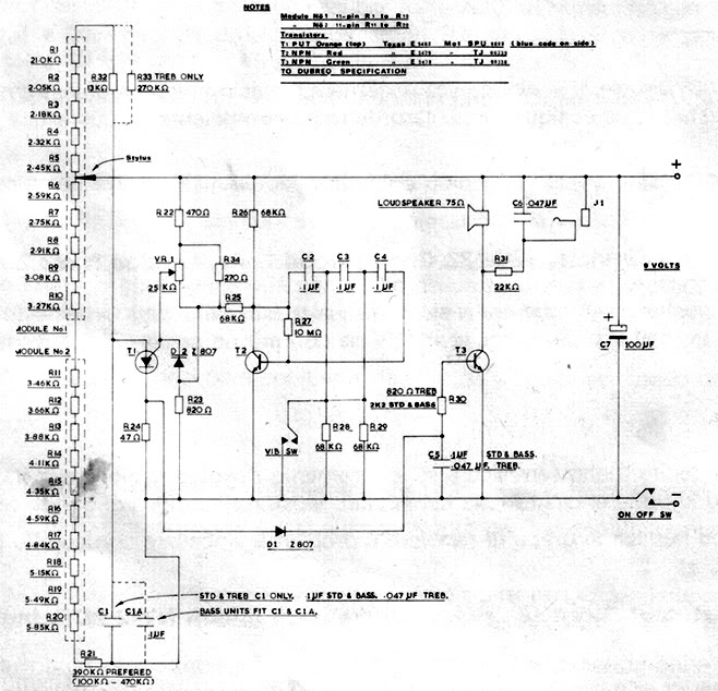
In summary, ensuring that the output volume of an amplifier is kept within safe limits is vital for protecting both the listener's hearing and the loudspeakers. By integrating volume control mechanisms, such as potentiometers, digital controls, or limiting circuits, an effective solution can be achieved to maintain audio quality and safety.Sometimes the output volume of amplifier is too high and hurts our ears. As well as hurting your ears, this incident could damage your loudspeaker. The circuit.. 🔗 External reference
Related Circuits
A recently discovered schematic appears to be authentic and does not include the 555 timer. Additionally, a picture of Brian Davis on this page shows him holding the etch mask, which does not exhibit any features resembling a socket...
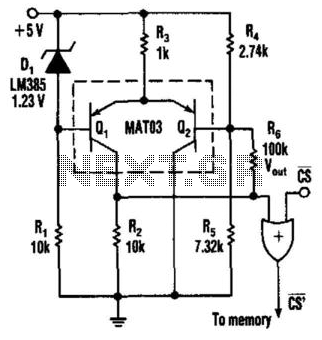
This circuit detects low-voltage supply conditions, down to 0.6 V. Diode D1 sets the trip point of the circuit. The circuit is useful for protecting memory circuits from accidental writes during low-voltage power supply conditions, which can cause other...
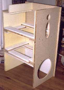
Building ESLs involves the use of tools and materials that if handled improperly can be hazardous. Please make sure you know how to use these things before you begin. By all means, use safety glasses at all times. If...
The entire circuit is powered from a very simple regulated ±15V power supply that is able to deliver about 2 A continuous duty and at least 6 A on musical peaks. Two three-terminal regulators with power transistors wrapped around...
The circuit-delay relay for speakers serves as a delay mechanism that prevents the immediate activation of speakers when the amplifier is powered on. This feature is designed to protect the speakers from potential damage caused by sudden power surges....
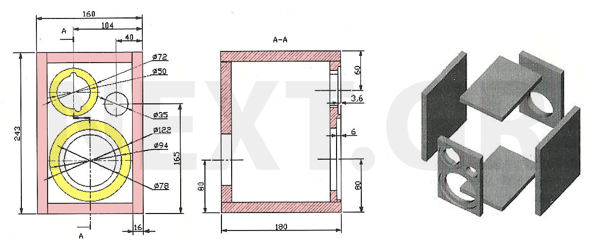
The speakers presented are notable for their compact size and exceptional sound quality. Often, home spaces are limited, making large speakers impractical. However, this does not imply a compromise on sound quality. The design is straightforward, cost-effective, and easy...