
Electrostatic Loudspeakers project
The construction of electrostatic loudspeakers (ESLs) requires careful attention to the selection of components and materials to ensure both performance and safety. The use of transformers is critical, with recommendations for tube amp output transformers rated for 4 ohm to 8K - 20K ohm impedance, capable of handling approximately 15-20 watts at low frequencies (around 30 Hz). Notable transformer brands include Tango, Triad, and Stancor, with an expected cost of around $50 each.
The diaphragm material is another vital component. Mylar or similar polyester films with a thickness of 5-6 microns are preferred for their acoustic properties. Sourcing from industrial plastic suppliers is advisable, ensuring that non-metalized films are used to avoid interference with sound reproduction. A typical roll might measure 1200 m by 1 m, costing approximately $85.
Coating the diaphragm for enhanced performance can be achieved using powdered graphite, dish soap, or antistatic solutions. The graphite, which can be sourced from local hardware stores, requires application using cotton balls to ensure even coverage. Alternative methods include using drafting ink designed for polyester films, which may provide a high resistivity coating.
The structural integrity of the ESL is bolstered by using perforated aluminum or steel for the front and back of the driver, with a recommended hole diameter of no more than 4 mm to maintain structural integrity and acoustic performance. Aluminum is favored for its weight and ease of cutting, although steel may be more cost-effective.
For the driver frame, acrylic or fiberglass PC board stock can be utilized. While fiberglass offers durability, it poses cutting challenges and health hazards due to dust. Acrylic is easier to work with but may require specific adhesives for proper bonding.
Adhesives play a crucial role in assembly. Epoxy is commonly used, but it does not bond well with Mylar, risking delamination under stress. An alternative is 3M's Scotchgrip #4693 contact cement, which provides a robust bond while allowing for easier disassembly if needed.
Finally, the high voltage bias supply is essential for the operation of ESLs, typically requiring a voltage range of 1000-5000 VDC. This can be achieved through a voltage multiplier circuit utilizing high voltage diodes and capacitors, with the option to use multiple supplies for individual speakers to simplify installation and reduce high voltage wiring complexities.Building ESLs involves the use of tools and materials that if handled improperly can be hazardous. Please make sure you know how to use these things before you begin. By all means, use safety glasses at all times. If would be foolish to trade your vision for the pursuit of audio ecstasy! 1) Transformers, one or two per speaker - use tube amp output transformers, 4 ohm:8K -20K ohm. I have used Tango CRD-8 ( 4:8KCT) transformers that I bought in Japan. You can use transformers by Triad, Stancor, etc. Just get units that are good for about 15-20 W at 30 Hz and give a large impedance (i.e. voltage) transformation. Expect to pay about $50 each for transformers. Tube amp output transformers are available from Antique Electronic Supply, 602-820-5411, and other sources. 2) Plastic film for speaker diaphragms- Mylar or other polyester, thin (5-6 microns), and large enough to make the size of driver you want to build.
This can be obtained from companies that make plastics for industry- this film is commonly used to make capacitors (don't get metalized film!). I bought a roll that is 1200 m long by 1 m wide for about $85 in Japan a few years ago. I have used about 15 m of it so far. I have heard of people using Saran-wrap, but I have never heard a driver built using it. If you're making small drivers, or experimenting, try it! It certainly won't cost much... 3) Powdered graphite, dish soap, or antistatic solution to coat diaphragm. Powdered graphite is available from K-mart or your local hardware store for lubricating locks. It will cost no more than $2 for enough to make about 50 speakers. Graphite has to be rubbed into the film using cotton balls. Dish detergent and antistatic solution will work also, and are easier to apply, but may not be "permanent".
I use graphite. Someone in Australia suggested that drafting ink formulated for drawing on "film" (the draftsman's name for polyester) will make a good, easy to apply, high resitvity diaphragm coating. I haven't tried it yet, but applying a colored liquid ought to be easy and make it easy to verify that it only went where you wanted it.
4) Perforated aluminum or steel- You need a piece for the front and the back of the driver. It should be flat and have about 60% or more open area (holes). Hole size? The stuff I use has holes that are about 3 or 4 mm diameter. The "rules of thumb" say don't use holes larger than about 1/4". Check your local Yellow Pages phone book for listings under Perforators, or Sheet Metal. Your local hardware store may have some available also. Aluminum is much easier to cut than steel, and it is much lighter weight, but may cost a little more than steel. If you buy from a perforator you can get them to cut the metal to size and roll it flat for you. 5) Acrylic or fiberglass PC board stock for driver frame. Fiberglass is hard to cut (you need a carbide blade), and the dust from sawing is a health hazard, but epoxy will bond to it.
Acrylic or other plastics are easier to work with, but epoxy may not form much of a bond to them (contact cement will probably work just fine). I have used both acrylics and PC board and for all it's trouble, I prefer the PC board material. You can get fiberglass from a PC board company- try to raid their scrap pile- and get them to cut the pieces to size for you.
We'll talk about thickness later. 6) Glue - Previously I recommended epoxy to hold the ESL together. Epoxy works fine for attaching the perforated metal to the insulator frame. The problem with epoxy is that it doesn't really bond to the mylar film. A little mechanical stress can break the very weak bond and allow the film to peel away. This can be an advantage. If you find that a driver doesn't work, if you assembled it with epoxy it will be easy to rip apart and rebuild. I have done some additional research and found a contact cement manufactured by 3M that works for attaching the film to the insulating frame.
Scotchgrip #4693 is the stuff to use. You put a little on one or both surfaces to be glued and let dry for 10-20 minutes. Then you put the two surfaces together and Voila!, instant bond. The bond is so good that the film will tear long before the glue lets go. Other contact cements may work well also. The only disadvantage is that once you've assembled the driver using contact cement, you have to live with it. If the driver doesn't work, you'll have to build another because you won't be able to tear the old one apart.
7) High voltage DC bias supply (1000-5000VDC, almost no current.) This can be made as a voltage multiplier that works off the power lines. You'll need high voltage diodes and capacitors, a few resistors, a circuit board and a line cord. You can get away with one supply, but one for each speaker is easier to deal with- you won't have to run high voltage wires all over your listening room.
See the Bias Supply section near the end of this document. 🔗 External reference
Related Circuits
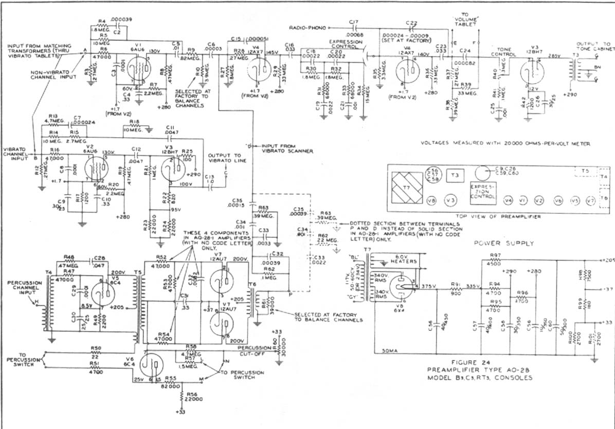
Construct a preamplifier intended to accept a 1/4" keyboard line-level signal and drive a Leslie 147 amplifier. The preamp will utilize a 12AX7 and 12BH7, following the design of a Hammond Organ preamp. The focus will be on the...
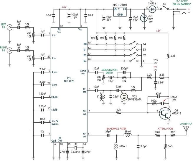
This stereo FM modulator circuit utilizes the BH1417F FM stereo transmitter integrated circuit (IC), which includes a stereo modulator for generating stereo composite signals and an FM transmitter for broadcasting an FM signal wirelessly. The stereo modulator produces a...
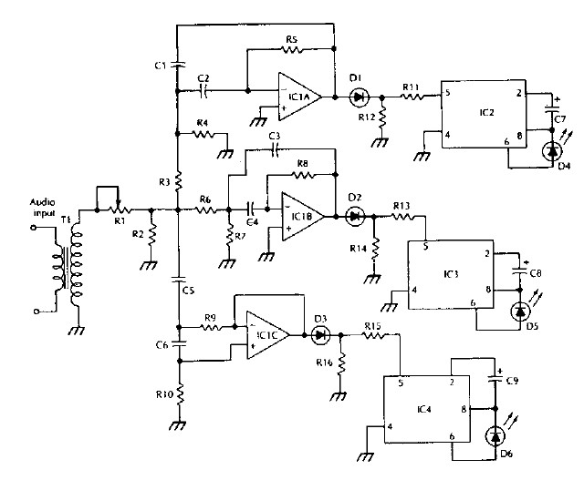
The LM 3909 LED flasher integrated circuit (IC) can be utilized to design various electronic projects. A circuit diagram illustrates the creation of a simple color organ using the LM3909 LED flasher IC. Three active filters process the audio...
The orange lines represent the positive voltage, while the yellow lines indicate the negative voltage, commonly referred to as ground. Wiring can be accomplished by soldering components directly to wires or by utilizing a small piece of perfboard or...
This project was inspired by a desire to create something unique rather than with the expectation of it becoming a practical transmitter. At the time of writing, the project is in the breadboarding phase, and a decision has yet...
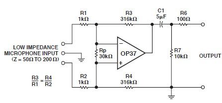
This microphone preamp schematic is an electronic circuit project utilizing the OP37 operational amplifier from Analog Devices. It functions as a fixed-gain transformerless microphone preamp, amplifying differential signals from low-impedance microphones by 50 dB, with an input impedance of...