
El-Cheapo Fluoro Ballast

This circuit is designed to efficiently ignite small fluorescent tubes without relying on the traditional filament heating method. The use of a voltage tripler circuit, consisting of three diodes (D1-D3) and high-voltage capacitors (6.8nF, rated at 2kV), allows for the generation of the necessary high voltage to initiate the gas discharge within the tube.
When the circuit is powered, capacitor C1 begins to charge through resistor R1. The charging process continues until the voltage across C1 reaches approximately 700V, which is the threshold voltage required for the gas inside the fluorescent tube to ionize. At this point, the gas breakdown occurs, and C1 discharges its stored energy into the tube. This discharge creates a conductive path, allowing AC current to flow through the tube, which is essential for its operation.
Once the tube is ignited, capacitor C1 serves a dual purpose. It not only continues to provide the necessary voltage to keep the tube lit but also acts as a ballast to regulate the current flowing through the tube. The inclusion of resistor R1 is critical; it ensures that the diodes do not shunt the tube during the positive half-cycles of the mains voltage, which could disrupt the operation of the circuit.
Overall, this circuit exemplifies a compact and effective solution for driving small fluorescent tubes, utilizing a combination of capacitive and resistive elements to achieve reliable ignition and sustained operation.This simple circuit can start small (15W or less) fluorescent tubes such as those used in PC board exposure and EPROM ultraviolet erasure boxes. As you can see, the tube`s filament heaters are not used. Instead, ignition is provided by a voltage tripler formed by diodes D1-D3 and the two 6. 8nF 2kV capacitors. At switch on, C1 charges up via R1 unt il the gas in the tube breaks down (around 700V). C1 then discharges through the tube, lowering the resistance enough to sustain continual AC current flow. C1 then continues to act as the ballast, with R1 included to prevent the three diodes shunting the tube on positive mains half-cycles.
🔗 External reference
Related Circuits
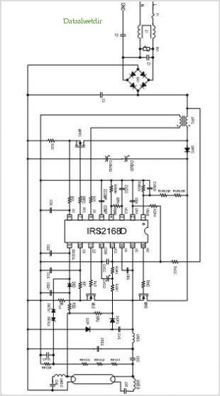
The following circuit illustrates a 14 Watt Compact Fluorescent Electronic Ballast Circuit Diagram. Features: it is similar to a 16 Watt circuit, 14 Watt. The 14 Watt Compact Fluorescent Electronic Ballast Circuit is designed to efficiently drive compact fluorescent lamps...
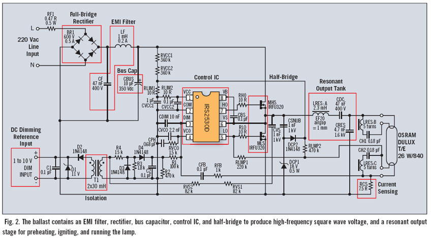
Fluorescent dimming systems can enhance visual comfort and lower utility costs through strategies such as daylight harvesting, demand reduction, and scheduled dimming. A dimming electronic ballast plays a crucial role in this system. To execute dimming functions, the ballast...
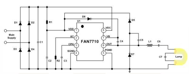
The FAN7710 Ballast Control IC is designed for use with compact fluorescent lamps (CFLs). This IC is developed using Fairchild's unique high-voltage process and system-in-package (SiP) technology. The FAN7710 is a highly integrated ballast control solution that provides efficient operation...
Gratitude is expressed to Don Klipstein for his contributions to this document. His website serves as a valuable resource for information related to lighting technology and includes additional articles on fluorescent and other discharge lamps. The fluorescent lamp represents...
The circuit diagram illustrates a dedicated electronic ballast circuit for a 16W2D single-ended energy-saving lamp. The RFI filter circuit consists of components such as zinc oxide varistors for protection, bridge rectifiers, a high-frequency oscillator, and an LC series output...
ISL83202IPZ is a subpackage of ISL83202. For the full description, please refer to ISL83202. The datasheet for ISL83202IPZ can be downloaded from the link provided below. By Intersil Corporation. The ISL83202IPZ is a component within the ISL83202 series, designed for...