
14 Watt Compact Fluorescent Electronic Ballast

The 14 Watt Compact Fluorescent Electronic Ballast Circuit is designed to efficiently drive compact fluorescent lamps (CFLs) with a power output of 14 Watts. This circuit is crucial for providing the necessary high-frequency signal that enables the ignition and operation of CFLs, ensuring optimal performance and energy efficiency.
The circuit typically comprises several key components: a transformer, a rectifier, a capacitor, and a control circuit. The transformer steps up the voltage to the required levels for lamp ignition, while the rectifier converts the AC input into DC. The capacitor smooths the output, providing a stable voltage to the lamp.
In operation, the electronic ballast initiates the lamp by applying a high voltage pulse to the electrodes, allowing ionization of the gas within the lamp. Once the lamp is ignited, the ballast regulates the current flowing through the lamp to maintain a steady light output, preventing flickering and extending the lifespan of the lamp.
The design of this ballast is similar to that of a 16 Watt circuit, allowing for compatibility with various lamp types while ensuring efficient energy use. The electronic ballast not only improves lighting quality but also reduces energy consumption compared to traditional magnetic ballasts, making it a preferred choice in modern lighting applications. Additionally, the compact design of the circuit allows for easy integration into various fixtures, enhancing versatility in installation.The following circuit shows about 14 Watt Compact Fluorescent Electronic Ballast Circuit Diagram. Features: similar to a 16 Watt circuit, 14 Watt .. 🔗 External reference
Related Circuits
This is a license to use the files to manufacture up to 12 boards. If additional boards are required, please make contact. It is important to note that the order must specify the intent to produce 12 or fewer...
The transformer OCL and capacitor C1 create a tank circuit, which is coupled with sufficient turns to drive the grid in the lower left-hand winding. The output circuit is connected through a separate winding. For optimal waveform characteristics in...

Various threads on ringer circuits have been observed, showcasing multiple variants, particularly concerning the types of transformers utilized, such as air core and step-down transformers. One notable circuit is the 12V-to-120V configuration, which employs a joule ringer that utilizes...

The ICL7665S Super CMOS Micropower Over/Under Voltage Detector features two low-power, individually programmable voltage detectors integrated on a single CMOS chip. It typically requires 3 µA for operation and is designed for battery-operated systems and instruments that need high...
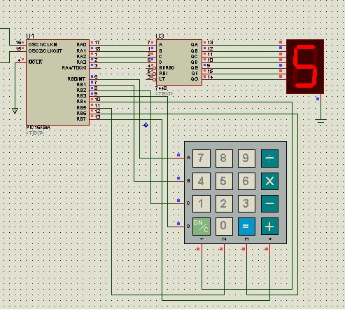
A keyboard key functions by establishing an electrical contact between the surface of the keyboard and the underlying circuit when the keytop area is pressed. This mechanism was utilized by some home computers in the early 1980s and has...
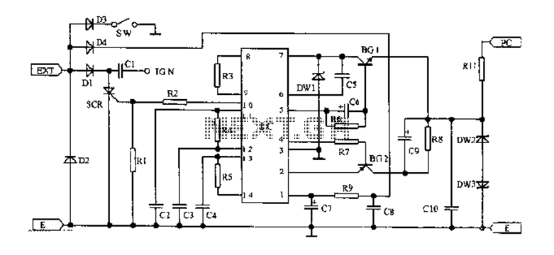
An AC magneto is connected to an external circuit. The output is rectified by diode D1 and stored in capacitor C1. Additional rectification is performed by diodes D4, along with resistors R9 and capacitors C7 and C8, which filter...