
Electric Field Mill Fabrication
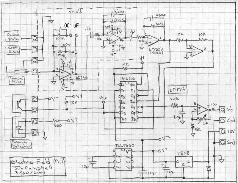
To construct the electric field mill, cut three strips of brass (approximately 0.5 x 2 inches), fold them in half, and drill holes so that the ledge is about 1.5 inches down from the top. Attach the plastic sensor plate hardware to the brackets and mount them inside the housing as illustrated. Drill a hole through a piece of 0.5-inch diameter Delrin, matching the motor shaft size, and drill and tap set screws. Cut a piece of stock the same size as the shaft and mount it as shown. Note that grounding the chopper rotor is essential, which may allow for fabrication of the mill without extending the shaft. It was necessary to cut the end off the motor shaft to fit the extender back sufficiently, resulting in some wobble on the extended shaft. Alternatively, the motor could be repositioned forward if necessary. Lay the chopper blades on a sheet of 0.015-inch thick brass, trace the outline of the chopper plate with a scribe, and cut it out using tin snips. Drill the center and cut to size using a nibbling tool.This page describes the construction of an electric field mill. This is a device to measure the electric field strength on earth due to the static electric field and the charge of clouds passing overhead. It can also be used to investigate static electricity effects. The body and chopper of the field mill are fabricated from a 4 inch diameter duct fan. The signal conditioning electronics uses a chopper blade position detector and a synchronous detector to reduce noise and recover the field sign (positive or negative) as well as magnitude (strength in V/m). 1. Martin A. Uman - Lightning, McGraw-Hill Book Company, New York (1969), 264 pages. Russian translation (1972), revised edition, Dover, New York (1984). (Available at Borders) The strength of the electric field could be measured, in principle, by placing a volt meter across plates placed some distance apart.
However, because the meter will have some input impedance (10 Meg typically), any voltage induced on the plates will quickly drain away, and would not be useful for measuring the static field. To make measurements of the static field, the chopper technique is used. The chopper blade is arranged over the Sense Plate and rotated so that it periodically shields, and exposes the Sense Plate to the electric field.
To properly do this, the Rotor must be grounded. The Sense Plate is grounded through a transconductance amplifier, which converts the Sense Plate`s ground current to a voltage. As the Sense Plate is exposed to the Field, the field induces ground currents as it attracts or repels charge from the Sense Plate.
As the plate is shielded from the field, the induced charge drains away. So the chopper induces an AC ground current which is proportional to electric field strength. This AC signal could then be rectified to drive a DC volt meter or be plotted on a scope. However, by doing this only the magnitude of the field, not the sign (positive of negative) would be measured. Also, any noise in the signal would also affect the output. The signal conditioning for this Field Mill uses a synchronous demodulation technique to preserve field sign information and reduce noise.
It works like this: The blade position is measured using an LED and photo transistor. The Position Sensor clock signal is used to effectively amplify the AC signal from the Sense Plate amplifier by either +1 or -1, depending on Rotor blade position. This has the effect of synchronously rectifying the AC signal, preserving sign. This rectified signal is then low pass filtered to remove ripple. Alternatively, this circuit function can be thought of as the mixing of two identical frequencies, resulting in output with frequency content at DC, and twice the input frequency.
The low pass filter then passes only the DC component. This line of thought will also show how noise at frequencies other that the position clock frequency are rejected. Cut 3 stripes of brass (about. 5 x 2 inches), fold about in half and drill. Drill three holes so that the ledge is about 1. 5 inches down from the top. Attach the plastic Sensor Plate hardware to the brackets and mount the brackets inside the housing as shown.
Drill a hole (the same size at the motor shaft. ) clean through a piece of. 5 inch diameter delrin. Drill and tap the set screws. Cut a piece of stock the same size as the shaft and mount as shown. Note: My goal was initially to insolate the chopper rotor, but then found grounding was required. So you may be able to fabricate the Mill without having to extend the shaft like this. I did have to cut the end off the motor shaft to fit the extender back far enough, and did end up with some wobble on the extended shaft You could move the whole motor forward as well if needed. Lay the Chopper blades on a sheet of. 015 thick brass. Trace the outline of the chopper plate using a scribe and cut it out using tin snipes. Drill the center and cut to size using a nibbl 🔗 External reference
Related Circuits
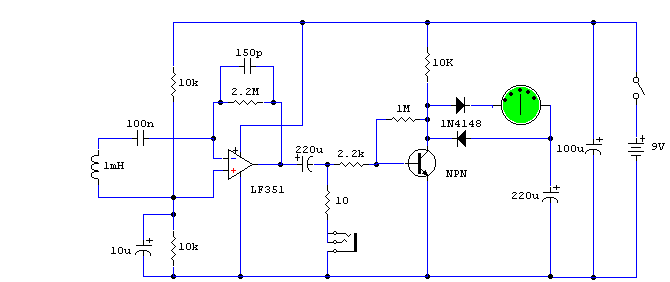
This circuit is a valuable tool that is easy to construct and more sensitive than many commercially available devices. It is based on an LF351 low-noise operational amplifier and a 1mF choke functioning as the sensor. Unlike most simple...
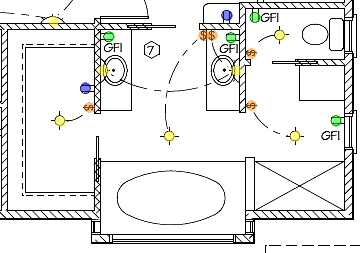
The following circuit illustrates the installation of a bathroom electrical wiring circuit diagram. Features include safety, energy savings, and enhancement of home functionality. This circuit diagram provides a comprehensive overview of the electrical wiring necessary for a bathroom installation. It...
A Transcutaneous Electrical Nerve Stimulation (TENS) device is essentially a machine designed to deliver electric stimulation to the nerves. This device was prescribed to the author. A Transcutaneous Electrical Nerve Stimulation (TENS) device is a therapeutic apparatus utilized for pain...
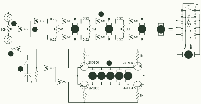
A friend and I are both trying to build a millipede. Because of obvious reasons, the millipede is NOT going to have 1000 feet. Instead, it is going to have 16 pager motors as feet. It will also have...
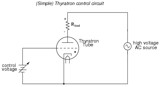
An often neglected area of study in modern electronics is that of tubes, more precisely known as vacuum tubes or electron tubes. Almost completely overshadowed by semiconductor, or "solid-state" components in most modern applications, tube technology once dominated electronic...
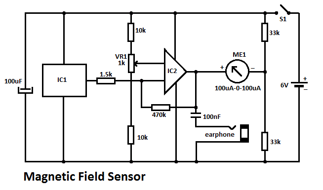
This DIY magnetic field sensor circuit is straightforward and capable of detecting both static magnetic fields and those that vary at audio frequencies. The unit is designed to be user-friendly and efficient. The magnetic field sensor circuit typically employs a...