
Installing Bathroom Electrical Wiring
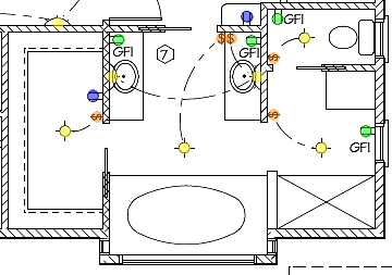
This circuit diagram provides a comprehensive overview of the electrical wiring necessary for a bathroom installation. It typically includes components such as lighting fixtures, outlets, and switches, all designed to meet safety standards and enhance energy efficiency.
Key features of the circuit include the use of GFCI (Ground Fault Circuit Interrupter) outlets, which are essential for bathroom environments due to the proximity to water sources. The GFCI outlets protect against electrical shock by interrupting the circuit when a ground fault is detected.
The circuit also incorporates energy-efficient lighting options, such as LED fixtures, which reduce overall power consumption while providing adequate illumination. The layout of the wiring should ensure that all fixtures and outlets are positioned for optimal functionality, taking into account the bathroom's design and usage.
In addition, the circuit should be designed to comply with local electrical codes, ensuring that all installations are safe and reliable. This includes proper grounding of all electrical components and the use of appropriate wire gauges based on the load requirements.
Overall, the bathroom electrical wiring circuit diagram serves as a vital tool for electricians and homeowners alike, facilitating a safe and efficient electrical system tailored for bathroom use.The following circuit shows about Installing Bathroom Electrical Wiring Circuit Diagram. Features: safety, energy saving, increase your home .. 🔗 External reference
Related Circuits

1999 Civic Wiring Diagram for Courtesy Lights Manual PDF. The 1999 Civic Wiring Diagram for courtesy lights provides a comprehensive visual representation of the electrical connections and components associated with the vehicle's interior lighting system. This schematic is essential for...
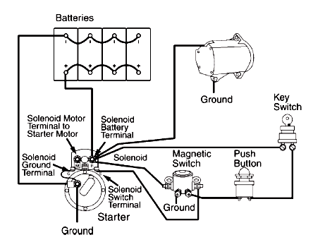
A circuit schematic for a basic heavy-duty electrical system that connects components such as the battery, starting motor, alternator, magnetic switch, ignition switch, and associated wiring. The heavy-duty electrical system circuit schematic is designed to provide reliable power management for...

The most likely issue with the wiring is the individual responsible for it. Apologies for the lengthy post, but providing more information and pictures may help clarify the situation. To create a comprehensive electronic schematic description, it is essential to...

The phase and neutral wires from the power source have already been connected to electrical appliances such as fans and light points. According to the UPS connection diagram, an additional phase wire should be connected to those appliances where...
Over time, various factors can lead to electrical issues in a Mustang. Components may become old and worn, or a wire might rub against something, exposing it to metal. Instances have been observed where body shops inadvertently crimp wires...
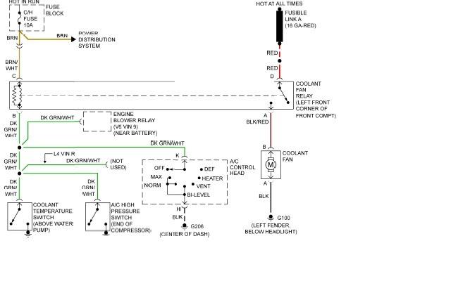
The following page outlines detailed information and the schematic of the 1985 Pontiac Fiero Wiring Diagram and Electrical System. The electrical system consists of: The 1985 Pontiac Fiero features a complex electrical system designed to support various components and functionalities...