
Electrical drive III

The design of the DIY Motion Platform III incorporates an H-bridge configuration that allows for bidirectional control of the motors, which is essential for applications requiring precise motion control. The use of MOSFETs, specifically the IRFB4610, enhances the efficiency and performance of the drive circuit due to their low on-resistance and rapid switching capabilities. The incorporation of a bootstrap circuit for the high-side MOSFETs ensures that they receive adequate gate drive voltage even during high-duty cycle operations, preventing issues related to insufficient gate drive that could lead to MOSFET failure.
The feedback mechanism integrated into the circuit is crucial for maintaining accurate position control. The combination of an op-amp and comparators allows for real-time adjustments based on the position feedback, ensuring that the platform responds correctly to control signals. The design also emphasizes the importance of dead time in preventing shoot-through conditions, which could cause excessive power loss and damage to the components. The adjustments made to the dead-time values demonstrate a commitment to optimizing performance while minimizing thermal dissipation.
Furthermore, the soft-start feature is a critical enhancement that prevents sudden surges in current during the initial power-up phase, thereby protecting the system from potential damage and ensuring a smoother operational start. This feature is particularly beneficial in applications where mechanical components may be sensitive to abrupt movements.
Overall, the design and implementation of the DIY Motion Platform III reflect a comprehensive understanding of power electronics and motion control systems, making it a valuable project for those with the requisite skills and knowledge in electronics.For DIY Motion Platform III, the electrical motion drive needed to be expanded to 3 channels. The small signal concept was not altered, but the MOSFET half-bridge was changed into full bridge. (H-bridge). The DAC converter was expanded to 4 channel version. Although the circuit is not extremely complex, it can be tricky to get it to work properly. It took me a couple of re-layouts and several modifications to get it stable. Since it consists of both sensitive digital circuits and high current switching power stages, the layout is extremely important. If you have some experience in building these kind of circuits, it`s good fun and will probably work.
Without any knowledge of power electronics, and no oscilloscope to do troubleshooting, I would recommend to buy commercial motor drivers. Price-wise, you`ll probably be cheaper building this circuit than buying three motor drivers, but this depends a lot on the price you can get the components listed.
Farnell is very expensive, but there must be others that offer the components for more reasonable price. The driving signals for the IC are made such that there is some dead-time between the switch-off of one Mosfet and switch-on of the other.
Without sufficient dead time, the two Mosfets could conduct simultaneously, shorting out the supply, thereby killing both Fets. The drive and position feedback are added together. The output of the opamp drives the inputs of two comparators, where the resistor network takes care that there is a small offset between the two comparators inputs.
The other inputs of the comparators are driven by a triangle waveform. (actually it`s a sawtooth but it does not make a difference) The resulting outputs of the comparators is shown at the right. Moving the DC voltages up will result in longer on-times of the low side Mosfet and shorter On times for the Hi-side Mosfet and visa versa.
The dead time between two transitions will remain constant. The H-bridge circuit is show above. Each high-side Mosfet drive has it`s own floating supply. This time I have made use of the bootstrap trick as shown in the IC spec. but I needed to add a special bias resistor (R12 and R16 via Vboost) to make sure that the Hi-side Mosfet floating supply will remain, also in 100% duty cycle conditions. Vboost is a voltage that is about 18V higher than the +BAT voltage. With this solution, the Mosfet drive always has correct gate drive supply, regardless the switching conditions.
Diodes D19 and D20 proved necessary to protect the drive IC`s from negative spikes. Although the H-bridge circuit has about double the component count of the half-bridge, it has the advantage that it needs only one single positive BAT supply, which does not need current sink capabilities. * Update version 2. 3: I have replaced the IRFP250 by IRFB4610. They have lower Rdson, but more importantly they have very fast body diodes and are especially designed for hard-switching configuration.
A part of the small signal section of the Motion drive is shown above. Some resistor values may need to be modified depending on the amount of actuator travel and the gear-ratio of the Position potmeter pickup. A change compared to the previous circuit is the implementation of soft-start: Now this is implemented in the small-signal chain.
(S3 and R23). During start-up, the relay is not activated, and R23 attenuates the error signal in such a way that the platform has only limited driving capability to move to the center point. When the softstart signal goes high, the relay switches off R23 and full drive speed is enabled. * Update version 2. 3: I have reduced the dead-time by lowering the values for R25/R26. This reduces dissipation in the MOSFETS. Dead-time of all 3 bridges need to be reduced, see full schematic at the bottom. The power supply of the Motion Driver is show above. Standard + and - 15V for the small signal supply. The delay for Battery switch and S 🔗 External reference
Related Circuits
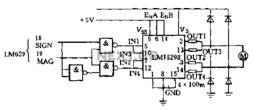
The LM629 PWM outputs directly drive the LM18298 dual H-bridge circuit, which functions as a switching amplifier. This configuration employs two H-bridges in parallel to control small DC servo motors. Additionally, the LM629 can be utilized for motion control...
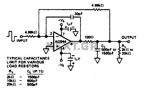
The circuit utilizes a 100-ohm isolation resistor that allows the amplifier to drive capacitive loads greater than 500 pF. This resistor effectively isolates high-frequency feedback from the load, contributing to circuit stability. Low-frequency feedback is returned to the amplifier's...
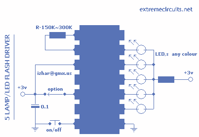
This circuit is based around HT2050 manufactured by HOLTEK semiconductors. It is a low cost, low-power C-MOS LSI designed for lamp and LED flash driver. It requires minimum external components. You can operate it with just two AAA cells...

The 1-Wire Net, or MicroLAN (by Maxim-Dallas), is a straightforward method for connecting slow devices such as sensors, relay drivers, and switches using basic components. These components include a 1-Wire protocol handler, an interface to the external world, and...
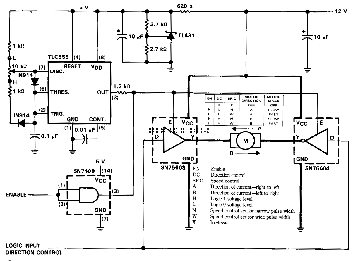
The figure illustrates a reversible DC motor drive application with adjustable speed control. The D inputs for these drivers are complementary and can be tied together and driven from the same logic control for bidirectional motor drive. The enables...
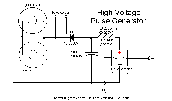
The ignition coil driver circuit described is a highly regarded design, reportedly created by Jochen Kronjaeger. It is intended to operate from a 230V source, although a modified version can function effectively at 120V. The circuit requires two ignition...