
Electrical isolation for the I2C bus with optocouplers

The described circuit utilizes optocouplers to achieve isolation between different segments of the I2C bus while maintaining signal integrity. The primary function of the SDA and SDA' lines is to facilitate communication between master and slave devices in an I2C setup. The transition of the SDA line to a logical '0' activates the optocoupler IC1, allowing current to flow through R2 and illuminating the LED. This action also influences the SDA' line, ensuring that it mirrors the state of the SDA line, thus reinforcing the integrity of the communication.
The symmetrical design of the circuit is crucial for ensuring that both lines can operate in tandem without interference. The lower section of the circuit, which handles the SCL line, mirrors the functionality of the upper section, ensuring that timing signals are also transmitted reliably. The inclusion of pull-up resistors (R1, A4, A5, A8) is standard practice in I2C bus designs, as these resistors help maintain the lines at a high state when they are not actively driven low. This prevents floating states that could lead to erratic behavior or false triggering of devices on the bus.
Furthermore, the slight increase in current draw due to the parallel LEDs is a consideration that should be accounted for in the overall design, particularly in low-power applications. Despite this increase, the circuit adheres to the I2C specifications, ensuring compatibility with standard I2C devices. Overall, this circuit design exemplifies a robust approach to isolating and managing data communication in an I2C environment, leveraging optocouplers for enhanced reliability.When the lines SDA (Serial DAta) and SDA 'are logical '1', the circuit is at rest with the result that optocouplers IC 1 and IC2 can not convey absolutely no information. But once the SDA line become the 'O', then the LED the IC 1 becomes conductive through the resistor R2.
At that time the line SDA 'and it becomes reasonable' O 'because of conductivity of the transistor of IC 1 and D2. This logic state remains on the right side of the channel. After the LED of IC2 can not properly polarized, and therefore unable to transfer back to the left. In this way, ensure that the circuit will never be 'stuck' to logical 'O'. As you noticed, the circuit is symmetrical. Thus, if the line SDA 'lead to logical' O ', then the SDA line will also acquire. The lower part of the circuit works like the above, except that here the signal moving is the SCL (Serial CLock). The R 1, A4, A5 and A8 are the usual restraint Elements 3.3 KO which should always be placed on the lines of bus 12C.
If the resistors are already co-dedemenes elsewhere in the channel, they can be received by this circuit. The current absorbed by the Bus lines are a little higher than expected due to the presence of LED diodes that optocouplers are parallel with the resistance straps.
Nevertheless, the value is still consistent with standard specifications 12C.
Related Circuits
A macro for a register is required for Lab 4, which utilizes a 4-bit bus for data input and a 4-bit bus for data output. This serves as a foundational example for creating similar macros for all components that...
This section of the I2C interfacing project focuses on constructing an acceleration sensor while also addressing two additional aspects: the advanced application of the PCF8591 chip (previously discussed in the context of the pressure sensor) and operating the bus...
The IEEE-1284 bus specifies a parallel printer bus with data transfer speeds exceeding 1 MBps. It defines a point-to-point asynchronous bi-directional interface. Devices can be either 1284 compatible (older parallel port devices) or 1284 compliant. The maximum recommended length...
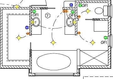
The following circuit illustrates the installation of a bathroom electrical wiring circuit diagram. Features include safety, energy savings, and enhancement of home functionality. This circuit diagram provides a comprehensive overview of the electrical wiring necessary for a bathroom installation. It...
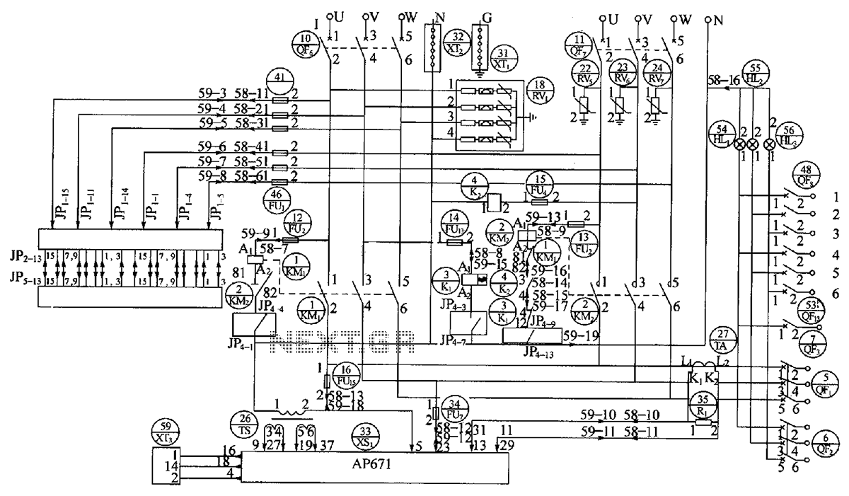
The OBO V20C functions as a lightning protection module, capable of handling a maximum lightning damage current of 40 kA. It includes a relay (k), a contactor (KM), a fuse (FU), and traffic lights (HL). The OBO V20C lightning protection...
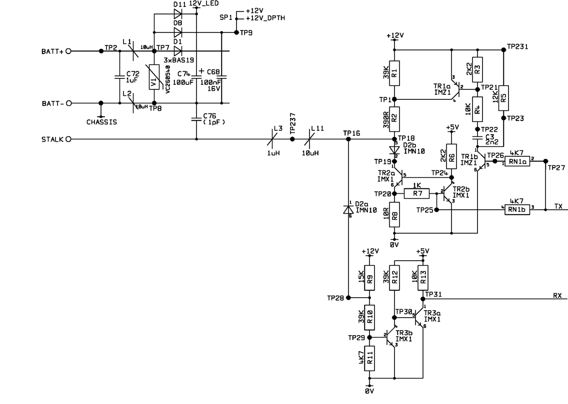
A project involves using a PIC microcontroller to communicate with the Raymarine SeaTalk bus. The schematic diagram for a Raymarine instrument shows a logic chip connected to the TX and RX connections on the right side, while the SeaTalk...