
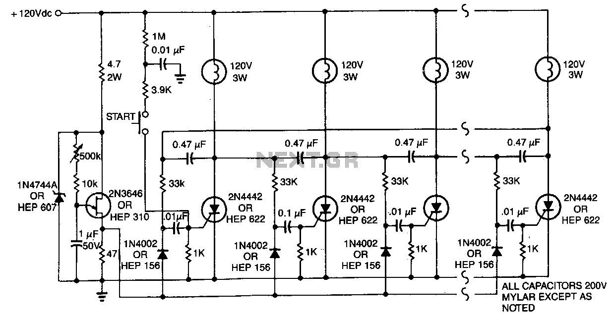
ELECTROMAGNETIC RING LAUNCHER

The electromagnetic ring launcher circuit serves as a practical demonstration of electromagnetic principles, employing a series of well-defined subcircuits to achieve its operation. The clock circuit utilizes a 555 timer (U5) configured in astable mode, generating a continuous square wave signal that serves as the timing reference for the entire system. This clock signal is essential for the synchronization of the countdown/display circuit.
The countdown/display circuit features a 74190 synchronous up/down counter (U3), which is specifically configured for countdown operation. This counter provides binary-coded decimal (BCD) outputs that are fed into the ECG8368 (U4), which acts as a latch/decoder and display driver. The outputs from U4 are directed to DISP1, a common-cathode seven-segment display, allowing for a visual representation of the countdown process.
The trigger circuit is integral to the operation of the launcher. It includes an MOC3010 optoisolator/coupler (U6), which provides electrical isolation between the control circuit and the high-power components. The output of the optoisolator drives a TRIAC (TRI), specifically an SK3665 rated for 200-PIV and 4-A, which controls the power delivered to the repulsion coil (L1). This arrangement ensures that the control signals do not interfere with the high current required to energize the coil.
The reset circuit is crucial for initializing the system and ensuring proper operation. It consists of a 7400 quad 2-input NAND gate (U1) and a second 555 timer (U2) configured in monostable mode. This configuration allows the circuit to be reset and prepared for a new countdown sequence, ensuring that the launcher is ready for subsequent operations.
Overall, the electromagnetic ring launcher effectively demonstrates the principles of electromagnetic propulsion through a well-coordinated sequence of operations facilitated by its various subcircuits. The combination of precise timing, visual feedback, and electrical isolation enables a reliable and educational demonstration of electromagnetic forces in action.The electromagnetic ring launcher is comprised of four subcircuits: a clock circuit (built around U5, a 555 oscillator/timer configured for astable operation), a count-down/display circuit (built around U3), a 74190 synchronous up/down counter with BCD outputs that is configured for countdown operation; U4, a ECG8368 BCD-to-7-segment latch/decoder /display driver; and DISP1, a commnon-cathode seven-segment display), a trigger circuit (comprised of U6), an MOC3010 optoisolator/coupler with Triac-driver output; TRI, an SK3665 200-PIV, 4-A Triac; and a few support components), and a reset circuit (comprised of U1, a 7400 quad 2-input NAND gate; U2, a second 555 os-cillator/timer configured for monostable operation; and a few support components). This circuit is that of a repulsion coil (L1) used to demonstrate the principle of electromagnetic repulsion by propelling a metal ring around the core of L1 through the air.
A countdown circuit is provided to count seconds before launch. 🔗 External reference
Related Circuits
One lamp at a time is lit in the string to give the appearance of a moving point of light. More: The ring counter circuit. The described circuit utilizes a ring counter configuration to create a sequential lighting effect in...
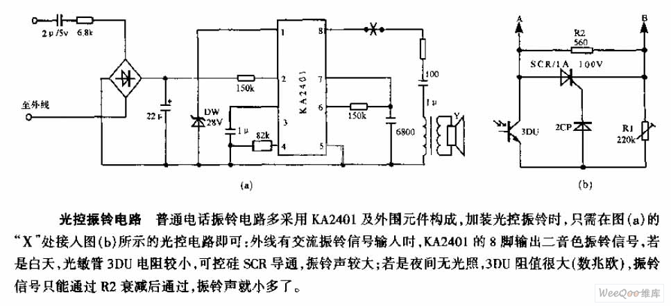
The average telephone ring circuit consists of the KA2401 integrated circuit and its associated peripheral components. To integrate a light-operated ring circuit, connect the designated part X in the provided diagram (picture a) to the light-operated circuit shown in...
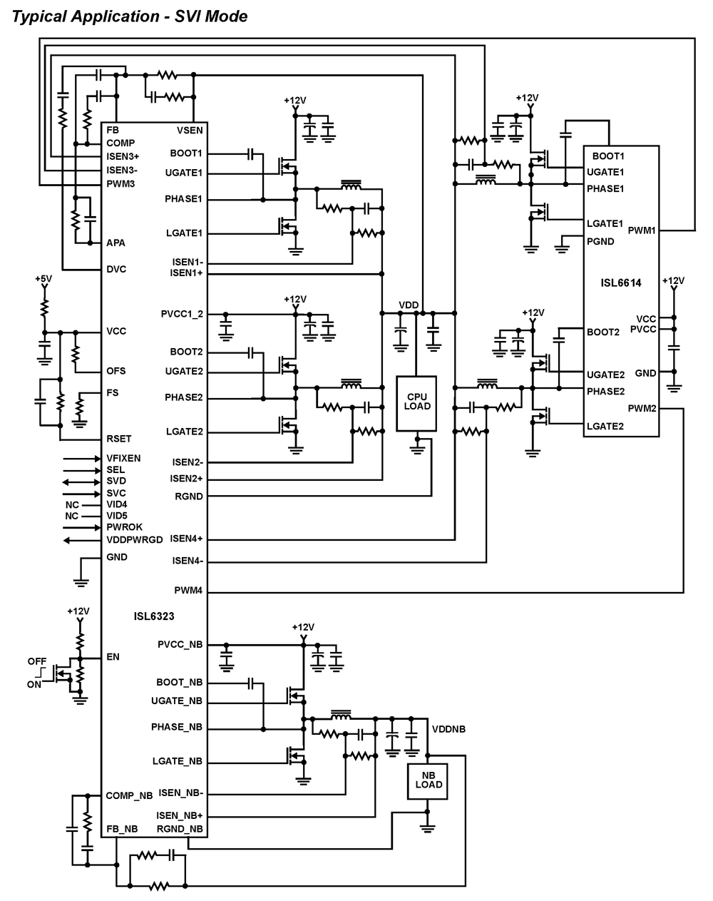
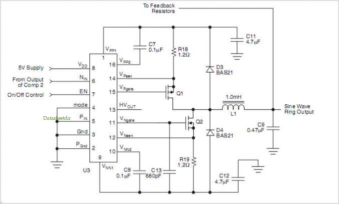
The ISL6323 dual PWM controller provides high efficiency and precise regulation through two synchronous buck DC/DC converters. It supports hybrid power control for AMD processors, operating via either a 6-bit parallel VID interface (PVI) or a serial VID interface...
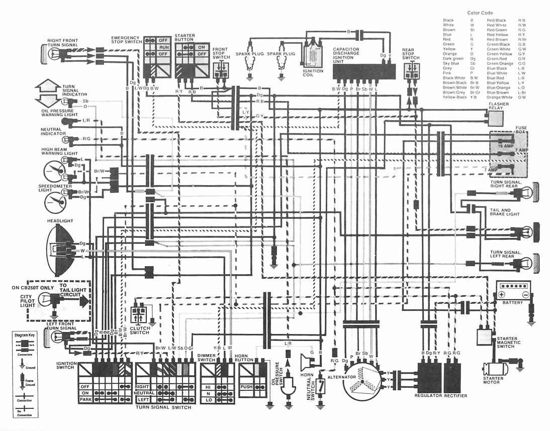
The following image depicts the electrical wiring connection diagram for the Honda Motorcycle CB400 (Hawk II). It illustrates the interconnections between various Honda components, including the turn signal, emergency stop switch, starter button, spark plug, capacitor discharge ignition unit,...
The HV739 is a monolithic single-channel, high-speed, high-voltage ultrasound transmitter pulser. This integrated, high-performance circuit is housed in a single 5x5 mm, 32-lead QFN package. The HV739 can deliver up to ±3.0 A of source and sink current to...
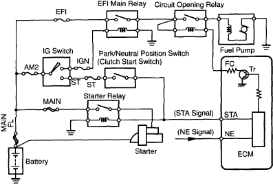
1997 Toyota Camry Fuel Pump Wiring Diagram. The fuel pump wiring diagram for the 1997 Toyota Camry provides a detailed representation of the electrical connections associated with the vehicle's fuel pump system. This diagram typically includes the power supply lines,...