
Electronic Dice
The circuit utilizes a 555 timer integrated circuit (IC) configured in astable mode to generate a continuous series of clock pulses. These pulses are transmitted to a CD4017 decade counter IC through a 10KΩ resistor, which serves to limit the current flowing into the counter. The CD4017 is a versatile 10-stage binary counter that sequentially activates its output pins (Q0 to Q9) with each clock pulse received. In this specific configuration, the output pin 5 (Q6) is linked to the reset pin (pin 15) of the CD4017. This connection effectively restricts the counter's operation to only six states (outputs 0 through 5), allowing for the creation of a six-sided dice simulation.
To visualize the output states, six light-emitting diodes (LEDs) are arranged in pairs, resulting in three pairs of LEDs. Each pair corresponds to specific outputs from the CD4017, and four transistors are employed to control these pairs. The transistors act as switches, turning the LEDs on or off based on the output from the counter. In instances where a single transistor is driven by multiple outputs, diodes are integrated to prevent potential short circuits, ensuring that the outputs do not interfere with one another.
Additionally, pin 13 of the CD4017, designated as the inhibit pin, is connected to the positive voltage supply through a 100KΩ resistor. This arrangement effectively disables the counter from advancing its state under normal conditions. However, the circuit includes a manual ROLL button which, when pressed, connects pin 13 to ground (negative voltage). This action permits the counter to resume its operation, thereby simulating the rolling of a dice. The overall design provides a simple yet effective means of generating random outputs, suitable for various applications requiring a randomized selection mechanism.The 555 timer IC is connected for Astable Operation, the clock pulses are fed to the 4017 IC via the 10K resistor. The 4017 is a 10 stage counter, output 6 (pin 5) is connected to RESET (pin 15), thus giving us a 6 stage counter , outputs 0 to 5.
6 of the LEDs are connected as 3 pairs, thus requiring 4 different signals, these signals come from the 4 transistors, which in turn are connected to the nescessary outputs of the 4017. Where a transistor is operated from more than one output, diodes are used to avoid a short circuit situation between outputs.
Pin 13 of the 4017 (INHIBIT) is connected to +ve via a 100K resistor to stop the counter from advancing, however pressing the ROLL button will connect pin 13 to -ve and allow the counter to advance, hence, throwing the dice. 🔗 External reference
Related Circuits
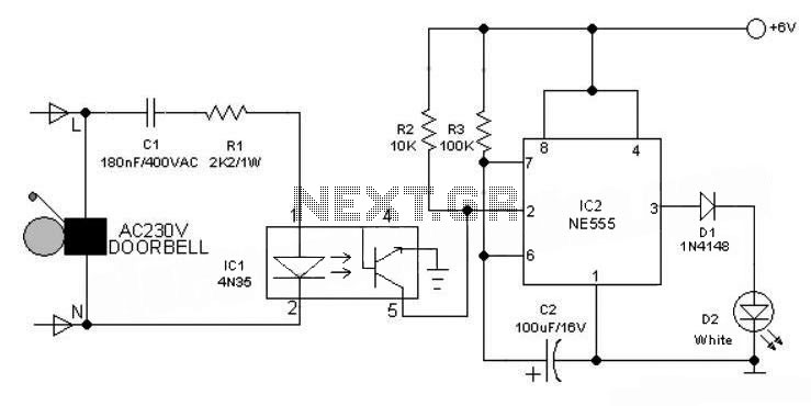
This 6V battery-operated doorbell light circuit can be connected in parallel with any existing AC 230V doorbell. When the doorbell switch is pressed, the bell sounds as usual, and the AC mains supply available across the doorbell is routed...
Stethoscopes are not only useful for doctors, but home mechanics, exterminators, spying and any number of other uses. Standard stethoscopes provide no amplification which limits their use. This circuit uses op-amps to greatly amplify a standard stethoscope, and includes...
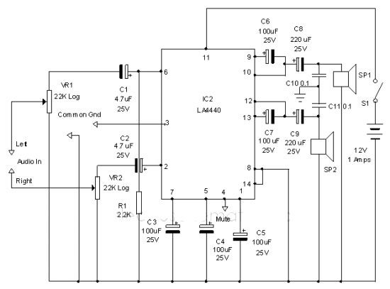
The LA4440 audio amplifier IC can be utilized to design a straightforward stereo power audio amplifier project, capable of delivering 6 watts of output power into an 8-ohm load. This audio amplifier IC features a minimal number of external...
The core component of this circuit is the UM3481 integrated circuit (IC), which operates with a 1.5-volt battery. It is suitable for applications such as electronic doorbells, toys, melody clocks, and music boxes. The UM3481 is engineered to play...

This electronic cricket is a gift for children. This simple battery-powered circuit can be utilized to play cricket matches with friends. Each LED in the circuit... This electronic cricket circuit is designed as an engaging and interactive toy for children,...

Here is a simple thermostat circuit that can be used to control a relay and supply power to a small space heater through the relay contacts. The relay contacts should be rated above the current requirements for the heater....