
Electronic Doorbell Light Schematic

The circuit operates by utilizing a 6V battery to power an LED light that activates simultaneously with the doorbell chime. The design includes a relay that is triggered when the doorbell is pressed. The relay connects the 6V battery to the LED light, illuminating it while the bell rings.
Key components of the circuit include a 6V battery, a relay capable of handling the current required for the LED, and an LED light source. The relay is essential for isolating the battery-powered circuit from the high-voltage AC supply, ensuring safety and preventing any potential damage to the components.
The LED is chosen for its low power consumption and high visibility, making it suitable for use as a doorbell indicator. The circuit can be easily integrated into existing doorbell systems without the need for extensive modifications.
To assemble the circuit, connect the relay's coil terminals to the doorbell switch, ensuring that the relay is rated for the voltage and current it will encounter. The LED is connected in series with a current-limiting resistor to prevent excess current from damaging it. The battery is connected to the common terminal of the relay, allowing the LED to light up when the relay activates.
This 6V battery-operated doorbell light circuit enhances the functionality of traditional doorbells by providing a visual indication of the doorbell's activation, increasing convenience and accessibility for users.This 6V battery operated doorbell light circuit can be connected in parallel with any existing AC230V doorbell. When anyone push the doorbell switch, the bell sounds as usual and ac mains supply available across the doorbell is routed to th..
🔗 External reference
Related Circuits
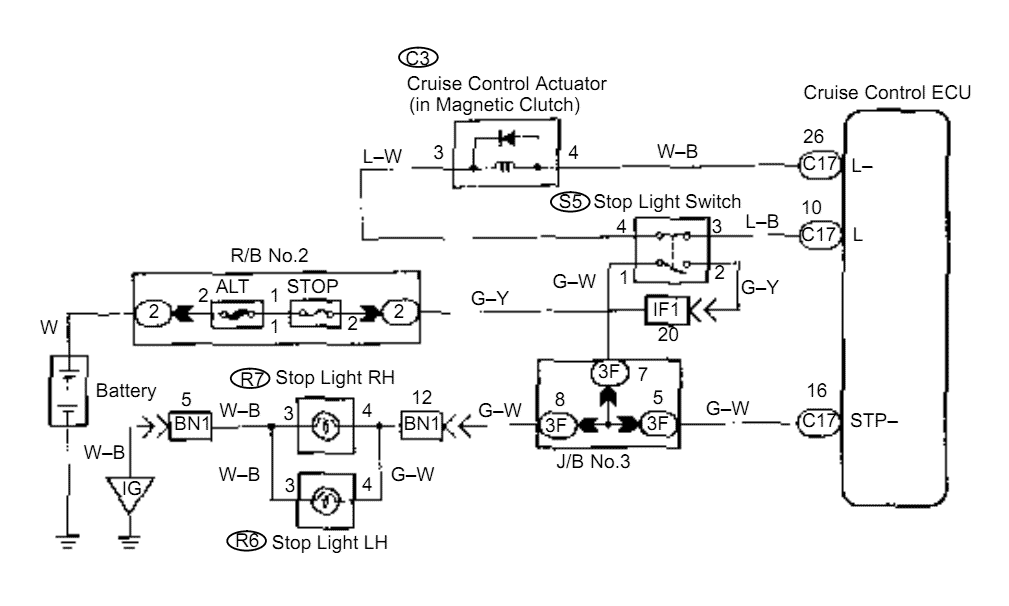
When the brake pedal is depressed, battery positive voltage normally applies through the STOP fuse and stop light switch to terminal STP of the ECU, and the ECU turns the cruise control off. A failsafe function is provided so...
What's so special about this circuit? Well, the first third-brake light I installed I had to pull a wire from the Third Brake Light all the way underneath the carpet to the brake-pedal-switch and I thought it would be...
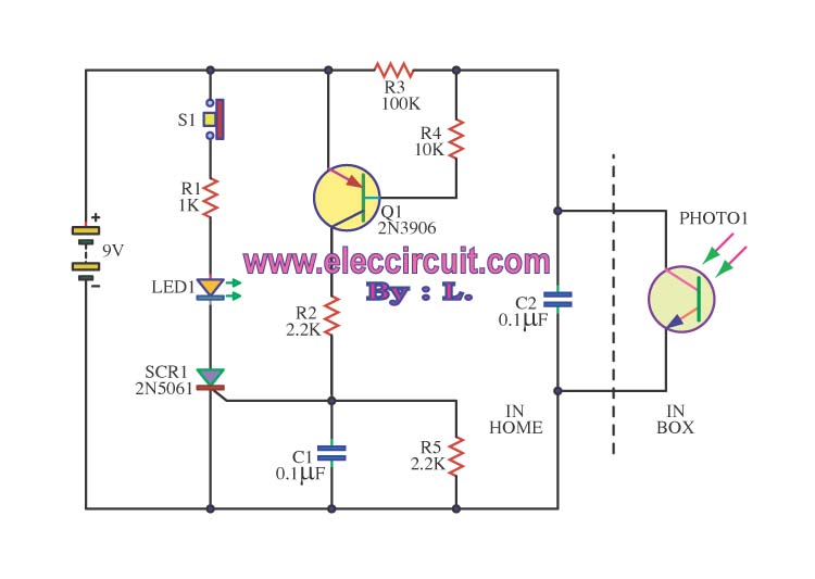
This is an integrated electronic mailbox circuit diagram designed for a front door. It activates when the door is opened. Additionally, when the cabinet photo detector is exposed to light, it will... The integrated electronic mailbox circuit is designed to...

Blue VALUES replaced by values in RED. Blue COMPONENTS removed from circuit. Red components added to circuit. More: Optional: move relay mute contacts to other side of C21. The provided description indicates modifications to an existing electronic circuit. The changes...
An electronic dice is a classic introductory project for individuals interested in electronics. It consists of a timer, counter, and several LEDs, forming a circuit that adds an engaging element to traditional board games. When the switch is activated,...
Many individuals find that they sleep well in natural environments, such as tents or wooden huts. This phenomenon is attributed not only to the healthy surroundings but also to our subconscious ability to perceive the Earth's natural magnetic fields....