
electronic door buzzer circuit schematic
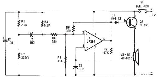
The electronic door buzzer circuit is designed to provide an audible alert when someone presses the push-button switch S1. The LF351 operational amplifier serves as the core component, functioning as an oscillator to generate sound signals. The configuration utilizes positive feedback to achieve oscillation, which is essential for producing the sound output.
Upon pressing the S1 switch, a voltage is applied to capacitor C2, which charges and subsequently influences the non-inverting input of the LF351. The operational amplifier is configured in a feedback loop that causes it to oscillate, creating a square wave output. This oscillation is then sent to the connected speaker, which converts the electrical signals into audible sound waves.
The choice of speaker impedance is crucial for the performance of the circuit. A speaker with an impedance between 40 to 80 ohms is recommended to ensure optimal sound output without overloading the amplifier. The circuit is powered by a 9-volt DC power supply, which provides sufficient voltage for the operational amplifier to function effectively.
The simplicity of this circuit makes it an excellent project for beginners in electronics, allowing them to understand the principles of oscillation, amplification, and sound generation. Additional components such as resistors and capacitors can be added for fine-tuning the frequency and volume of the buzzer, enabling customization based on specific requirements.This electronic door buzzer circuit schematic has a very simple function and is very easy to build. This door buzzer circuit use a LF351 operational amplifier and other few common electronic components. When the S1 push-button is depressed an initial positive voltage is placed on the C2 and the non-inverting terminal of the LF351 operational ampl
ifier and the circuit will oscillate at a low frequency. The used speaker for this project must have a impedance between 40 -80 ohms. The door buzzer electronic circuit need to be powered using a 9 volts DC power supply. 🔗 External reference
Related Circuits

The BiMOS CA3140 operational amplifier offers excellent orientation capabilities for high bandwidth signal inputs and can swiftly adjust the energy output at its terminal CA33IO WINE. The CA3140 can also operate close to the negative supply rail. If the...
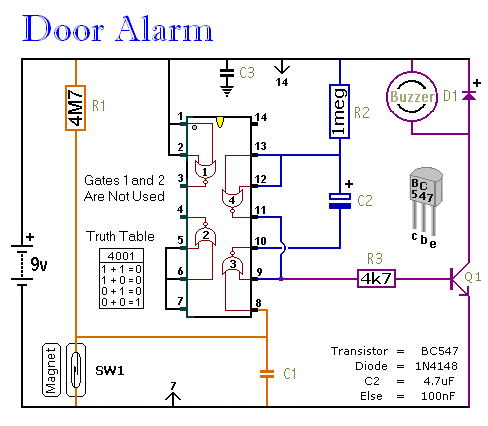
This is a straightforward and easy-to-assemble multi-purpose alarm system. It can be constructed using stripboard or veroboard along with a few inexpensive, readily available components. The alarm is designed to be installed on doors, windows, sheds, garages, cupboards, and...

A highly stable 60-Hz sine wave can be delivered with this circuit, which offers a different and much simpler approach to achieving a stable amplitude. Capacitor coupling in the last stage removes any DC component caused by unequal Zener...
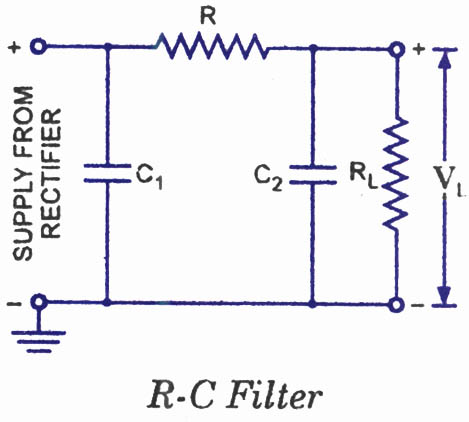
The disadvantages of pi-filters include higher costs, increased weight, larger size, and the external magnetic field generated by the series inductor. These issues can be mitigated by substituting the series inductor with a series resistor, referred to as an...
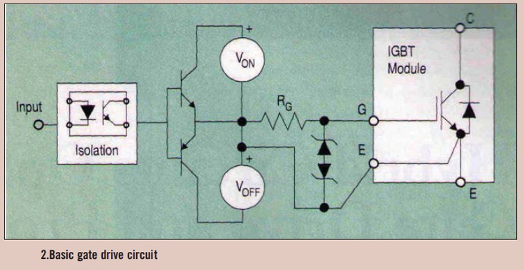
High power IGBT modules utilize hybrid integrated circuit (IC) gate drives that incorporate protection circuits, which implement desaturation detection or real-time control. High power Insulated Gate Bipolar Transistor (IGBT) modules are essential components in various high-efficiency power conversion applications, such...
Here, S1 and S2 are normally open, push to close, press button switches. The diodes can be red or green and are there only to indicate direction. You may need to alter the TIP31 transistors depending on the motor...
Warning: include(partials/cookie-banner.php): Failed to open stream: Permission denied in /var/www/html/nextgr/view-circuit.php on line 713
Warning: include(): Failed opening 'partials/cookie-banner.php' for inclusion (include_path='.:/usr/share/php') in /var/www/html/nextgr/view-circuit.php on line 713