
electronic doorbell circuit

This door alarm circuit is designed for simplicity and efficiency, making it suitable for various applications in residential or commercial settings. The HT-2811 sound chip is capable of producing high-quality audio output, ensuring that the chime is both pleasant and attention-grabbing. The CMOS 4026 driver IC is crucial for displaying the visitor count, allowing for easy monitoring of foot traffic.
Operating within a voltage range of 2.4 to 3.3 VDC ensures compatibility with a wide array of power sources, including batteries and low-voltage power supplies. The minimal standby current is an essential feature for battery-operated applications, extending the overall lifespan of the device.
The inclusion of a reset switch facilitates quick resetting of the visitor count, making it user-friendly. The common cathode 7-segment display provides clear visibility of the count, while the ability to enable or disable the display with a switch allows for further power savings when the device is not in active use.
The timing components, particularly the resistors and capacitors used to shape the chime envelope, can be fine-tuned based on user preferences. This adaptability allows for customization of the chime's characteristics, ensuring that it can be tailored to fit the specific needs of the installation environment.
The debouncing mechanism implemented through the resistor-capacitor network is critical in preventing erroneous counts due to mechanical bouncing of the doorbell switch. By ensuring that only a single count is registered for multiple rapid presses, the circuit maintains accuracy and reliability.
Overall, this door alarm circuit design represents a well-thought-out solution that combines functionality with user-friendly features, making it an excellent choice for those seeking an efficient visitor alert system.This is a design for a door alarm circuit, but in this design using electronic system. This circuit uses a synthesized sound chip from Holtek, the HT-2811. This circuit reproduces the sound of a "ding-dong" chiming doorbell. Additionally, the circuit includes a CMOS 4026 counter display driver IC to count your visitors. This is the figure of the c ircuit. The operating voltage must remain within 2. 4 to 3. 3 VDC and standby current is minimal. The reset switch zeroes the count, and the 7 segment display is a common cathode type. To save power consumption the display can be enabled or disabled with a switch as shown in the above diagram. The count will still be held in memory. The envelope of the chime is set by the 220k, 330k, 3u3 and 4u7 resistors and capacitors. These values are the manufactures default values, but may be adjusted to alter the length and delay of the chime.
The combination of the 2k2, 22k and 47u resistor capacitor network has a double function. It provides a de-bouncing circuit for the bell press and at the same time has a sufficiently long time constant. This ensures that anyone rapidly pressing the doorbell switch, only advances the count once. The 47u capacitor may be increased in size, if needed. 🔗 External reference
Related Circuits
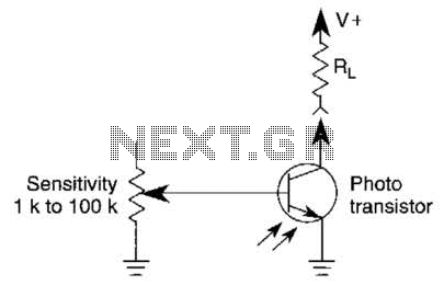
A variable resistor is utilized to adjust the light-level response of a phototransistor. Phototransistors exhibit higher light sensitivity compared to photodiodes; however, they typically demonstrate a lower frequency response. A variable resistor, often referred to as a potentiometer or rheostat,...
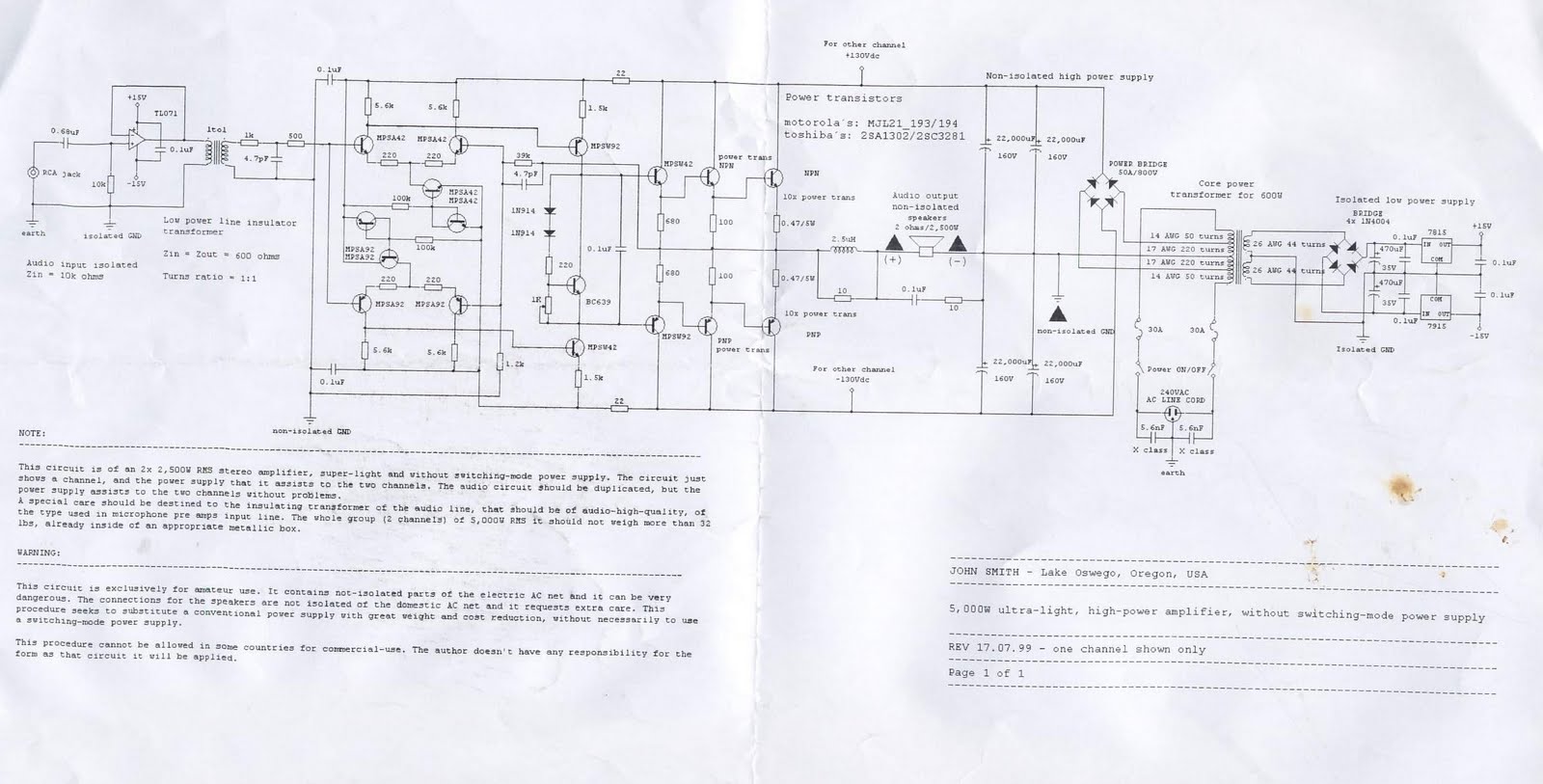
This device is a 2x2, 500W RMS stereo amplifier, designed to be super-lightweight and equipped with a switching-mode power supply. The device features a single channel display and specifies the power output it provides to both channels. The audio...
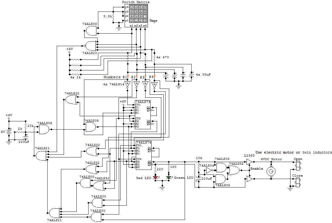
This circuit is an electronic locker controlled by a combination of switches (a code). It features a switch matrix located on the locker door, consisting of a unit of switches arranged in four rows and four columns, totaling eight...
This circuit features a simple, highly sensitive capacitive ON/OFF switch pad that changes the state of a latch and activates an LED without requiring physical contact. The pad can be insulated, and a range of 12mm is easily achievable...
A user has been experimenting with modifications to a budget-friendly MXL V67s microphone to enhance its performance, specifically aiming to improve the condenser quality until a higher-end model can be acquired. The MXL V67s is a popular choice among budget-conscious...
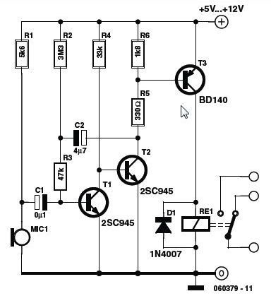
A high-quality and straightforward intercom circuit utilizing only three transistors. By pressing switch S2, the circuit generates ringing signals. To create a two-way intercom, two identical circuits can be constructed and combined as illustrated in diagram 2. The circuit's...
Warning: include(partials/cookie-banner.php): Failed to open stream: Permission denied in /var/www/html/nextgr/view-circuit.php on line 713
Warning: include(): Failed opening 'partials/cookie-banner.php' for inclusion (include_path='.:/usr/share/php') in /var/www/html/nextgr/view-circuit.php on line 713