
Electronic fly disinfestation
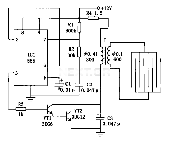
The electronic fly killer circuit is designed for effective pest control by generating a high-voltage electric field that kills flies upon contact. The core of the system is the astable multivibrator configuration created by the ICL 555 timer IC, which oscillates at a frequency suitable for generating the desired square wave output. The values of resistors R1 and R2, along with capacitor C1, are crucial for setting the frequency and duty cycle of the output waveform.
The transistors VT1 and VT2 function as switches that allow the low-voltage square wave signal to control a higher voltage, which is necessary for the operation of the step-up transformer. This transformer is designed to increase the voltage to a level sufficient to create a lethal electric shock when flies come into contact with the grid formed by the spaced wires.
The high-voltage transformer is configured to produce a secondary output that can reach several kilovolts. This high voltage is essential for ensuring that the device is effective in killing flies and deterring them from the area. The wire mesh, made from No. 14 gauge wire, is arranged with a spacing of approximately 6 mm to prevent larger insects from escaping while still being effective against flies.
Safety is a critical consideration in the design of this device. To prevent accidental contact with the high-voltage components, the fly killer should be mounted securely at a height of several meters above the ground. This ensures that children and pets cannot inadvertently come into contact with the electrified grid. Additionally, the device should be fixed firmly to prevent it from being knocked over, which could expose the high-voltage components and pose a safety risk. Overall, this electronic fly killer circuit represents an efficient and effective method for controlling fly populations in a variety of settings.Electronic Fly utilizes high voltage applied to the power line voltage pulse OCS killed flies. Use the following web site when the bait to attract flies, fly Fly online for all to be able to kill the flies. Fly electronic circuit as shown, when the base integrated circuit ICl 555 and the resistor Rl, R2 and the capacitor Cl form astable oscillator circuit, from the foot of ICl output frequency of about 30Hz, 10% duty cycle of continuous square wave. The square wave is coupled via a resistor R3 to the transistor VTl, VT2, promote step-up transformer T boosted amplification, so connected to the high-voltage transformer with a secondary IED kV grid in order to achieve the function of killing flies.
Fly net usable No. l4 wire production, the adjacent wire distance of about 6mm. In order to prevent a child inadvertently high-voltage grid, fly disinfestation should be placed in the ground a few meters high, and should be fixed firmly.
Related Circuits
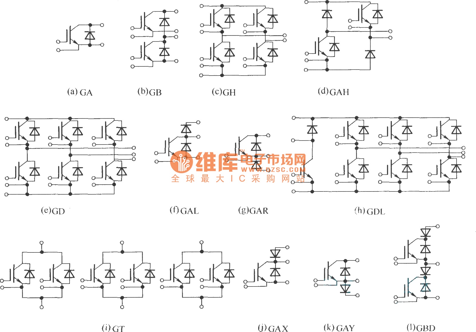
This document describes various electronic modules, including: (a) a single switch module; (b) a two-unit half bridge module; (c) an H bridge (single-phase bridge) module; (d) an asymmetrical H bridge module; (e) a three-phase bridge (six-unit or inverter bridge)...
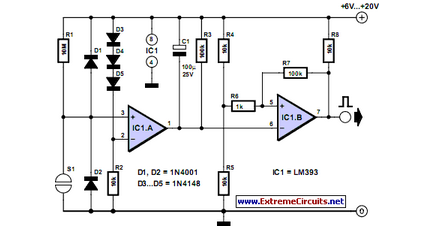
Mechanical contacts have the disadvantage that they wear out. That is why it is practical to use an electronic touch switch in some situations. The electronic touch switch serves as an effective alternative to mechanical contacts, addressing the issue of...
The controllable multivibrator, as illustrated in figure 14-40, consists of a 555 timer along with resistors RA, RP1, and capacitor C1. The oscillation frequency is influenced by the control voltage applied to pin 5. This control voltage is determined...
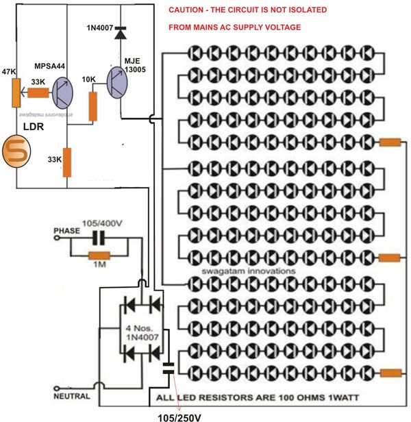
At times, it is quite frustrating to see street lights remaining switched on even during broad daylight. The current circuit for an automatic night light can effectively address this issue. This article explains how to construct such a system....
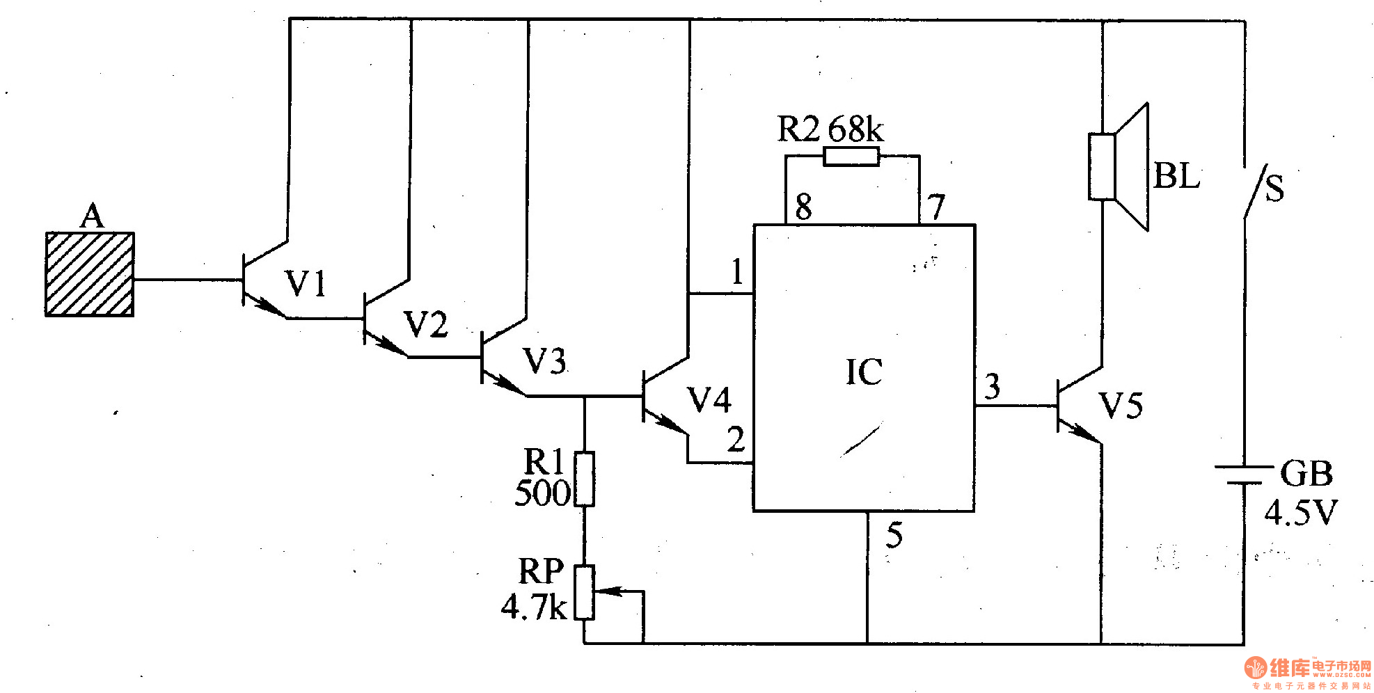
The inductive electronic doorbell circuit consists of an inductive electronic switch and a music generator circuit, as illustrated in Figure 3-115. The inductive electronic switch circuit includes an inductive electrode A, transistors V1-V4, a resistor R1, and a potentiometer...
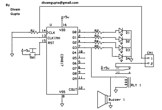
The Hand Steadiness Tester is a game which tests the steadiness of your hand. The player has to take the ring from one end to another end without touching it to the wire. In this the player gets 4...