
555 simple electronic keyboard circuit
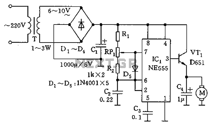
The controllable multivibrator circuit utilizes the 555 timer in an astable configuration, allowing it to generate a continuous square wave output. The frequency of the output waveform is primarily determined by the values of the resistors RA and RP1, as well as the capacitor C1. The control voltage at pin 5 plays a significant role in modulating the frequency of oscillation. By adjusting the voltage at this pin, the duty cycle and frequency can be altered, providing a means for external control over the timing characteristics of the circuit.
Resistors R1 to Rn and RB form a voltage divider network, influencing the voltage level seen at pin 5. The conduction state of the transistor VT1 further modifies this voltage, as it can either allow or block current flow, thereby affecting the voltage divider's output. When VT1 is in the active region, it allows the control voltage to rise or fall depending on the input signal, thereby dynamically adjusting the frequency of oscillation.
The output from the 555 timer can be used to drive various loads or can be fed into additional stages for further signal processing. This multivibrator configuration is widely used in applications such as pulse width modulation, tone generation, and timing circuits, making it a versatile component in electronic design. The careful selection of component values and the configuration of the circuit will determine the performance characteristics, such as frequency range and stability, making it essential to consider these factors during the design process.As the figure 14-40 shows, the controllable multivibrator is composed of the 555 and RA, RP1, C1, the oscillation frequency is related with the control voltage (pin-5), but the voltage of pin-5 depends on the partial voltage of R1?Rn and RB, and it is related with the conduction situation of VT1. The VT1 works in the amplifier region, voltage of electrode c.. 🔗 External reference
Related Circuits
The circuit utilizes a 555 timer as the core component to create an astable multivibrator. The oscillation period T is given by the formula T = 0.693 (R1 + 2R2) C1, which corresponds to an oscillation frequency of approximately...
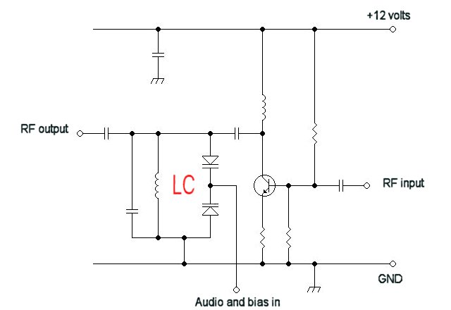
For a fixed frequency transmitter, a common method is to use a resonant quartz crystal in a crystal oscillator to establish the frequency. In transmitters where the frequency must be variable, several options are available. It is often the...

This optodetector measures the position of the ball by the amount of light transmitted by the infrared LED. It generates a linear signal across the small area of the detector, rather than simply providing an "on" or "off" output....
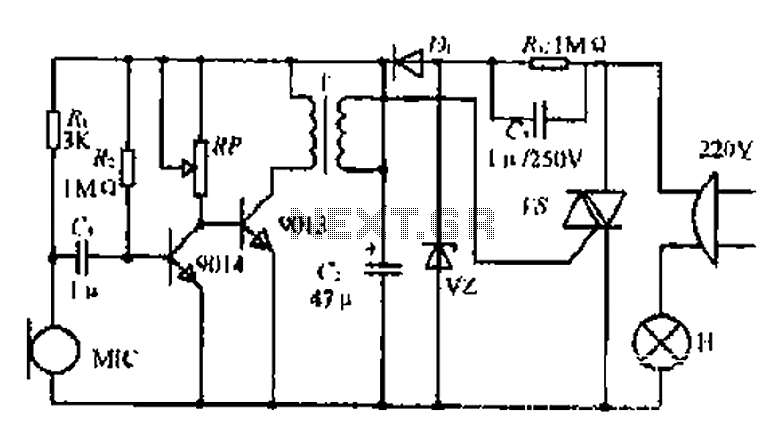
22W by Ct and R, RC Buck, rectified by n. c, filtering. vz 3V DC regulated output power, before U, V2 and MIC power supply. When the audio signal reaches the beam, the microphone MI converts acoustic energy into...
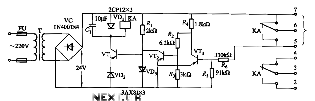
Another JYB type liquid level controller internal circuit is shown. This circuit employs a Schmitt trigger configuration, enhancing the reliability of the action level controller. The JYB type liquid level controller utilizes a Schmitt trigger circuit composed of transistors VT2...
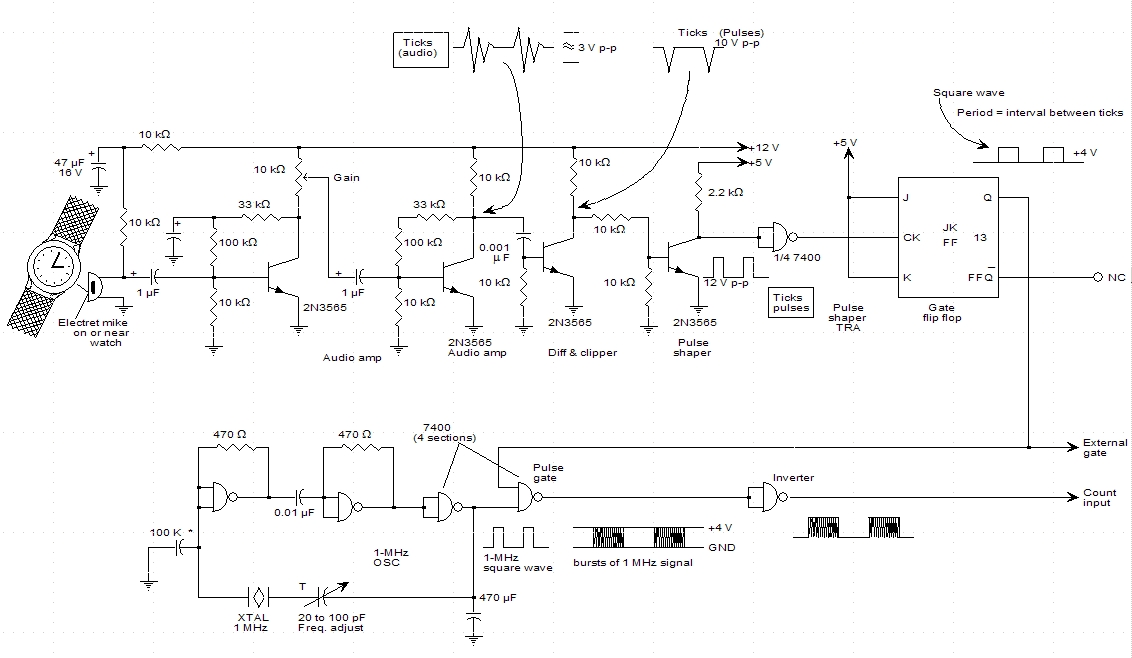
A schematic for a watch timer was found in a hobby electronics book. The circuit adapts a frequency counter to measure intervals. Watch ticks are clipped, shaped, and formed into a square wave. This square wave is utilized to...
Warning: include(partials/cookie-banner.php): Failed to open stream: Permission denied in /var/www/html/nextgr/view-circuit.php on line 713
Warning: include(): Failed opening 'partials/cookie-banner.php' for inclusion (include_path='.:/usr/share/php') in /var/www/html/nextgr/view-circuit.php on line 713