
Electronic sound control flooding imitation circuit design
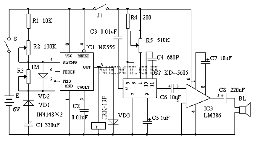
The electronic schematic for the meowing sound repeller consists of three main sections: the time control circuit, the meow generation circuit, and the power amplifier circuit.
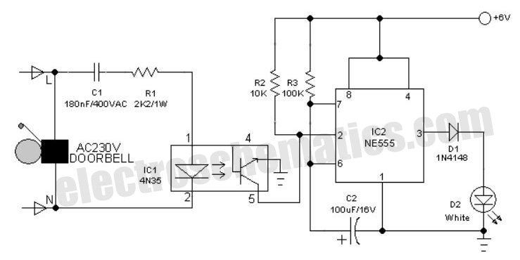
1. **Time Control Circuit**: This section is built around the NE555 timer IC, which is configured in astable mode. The configuration allows the timer to generate a square wave output at a frequency determined by the values of resistors R2 and R3 and the timing capacitor. The duty cycle can be adjusted by varying the resistance values, thus enabling the user to set the frequency and duration of the meowing sounds. The output from pin 3 of the NE555 is a pulse that triggers the relay.
2. **Meow Generation Circuit**: The KD-5605 CMOS IC is utilized for sound synthesis. This integrated circuit is capable of generating audio frequencies that mimic the sound of a cat meowing. The output from this IC is connected to the input of the power amplifier. The frequency of the generated sound can be fine-tuned by adjusting the internal parameters or external components connected to the KD-5605.
3. **Power Amplifier Circuit**: The LM386 is a low-voltage audio power amplifier that amplifies the meowing sound generated by the KD-5605. With its high gain and low distortion characteristics, the LM386 is ideal for driving small speakers. The output from the LM386 is connected to the speaker, which produces the audible sound that deters rats.
The relay in the circuit acts as a switch that controls the power flow to the meow generation circuit, ensuring that the sound is only produced when the NE555 timer is active. The relay's normally open contact allows for the integration of additional circuits or features if desired.
Overall, this circuit design is not only cost-effective and straightforward but also provides a practical solution for pest control using sound. The assembly requires basic electronic skills, and once constructed, it is typically ready for use without extensive troubleshooting. Cats are predators of rats, the use of electronic devices to simulate mew Repeller is an effective method. Because it is an electronic device, mew big or small, can be fast or slow, short or long intervals, and the circuit structure is simple, low cost, suitable for home-made electronics enthusiasts. Circuit works : by the time control circuit, mew generation circuit, power amplifier circuit. Time control circuit is by the time base circuit IC1NE555 its external RC components, diodes and other components.
It is a variable duty cycle pulse oscillator, which controls the duty cycle of the R2 and R3. Mew generation circuit consists of a CMOS integrated circuit IC2KD-5605 as the use of storage technology inside the circuit will mew cured. Cheap generic small power amplifier power audio amplifier integrated circuits IC3LM386, which is characterized by very few external components, wide voltage range, low distortion, simple assembly.
Close the power switch S, IC1 will power work in IC1 output terminal pulse output pin continuously. When a laser pulse excitation relay J pull its normally open contact J1 is turned on, so that a subsequent circuit receives power while work occurs mew, every triggering IC2, there soon meow output power is amplified by IC3 promote the loud speaker BL realistic sound. So that the mice heard faint, to achieve the purpose of the drive rats. Select IC1 components selected 555 base integrated circuit; IC2 selected KD-5605 audio integrated circuits; IC3 selected LM368.
Relay selection JRX-13F small relay, speaker BL should choose 8, 3W speaker or dedicated number above drum speaker, Wu rest of the device specific requirements. After the installation is complete circuit, as long as the line is correct, generally without debugging can be used normally.
Related Circuits
It was one of those days when learning chemistry, philosophy, and literature seemed necessary. Contemplating my plans for the day, I decided to embark on a project that I had wanted to undertake for a long time but had...
Standard serial interfacing of a microcontroller (TTL) with a PC or any RS232C standard device requires a TTL to RS232 level converter. A MAX232 is used for this purpose. It provides a 2-channel RS232C port and requires external 10µF...
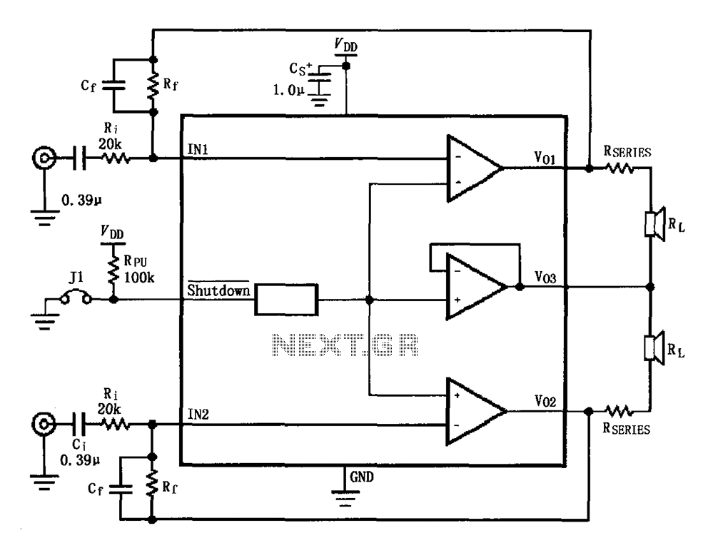
The circuit for the LM4910 is designed to minimize output noise and reduce power consumption. The output noise is attenuated by utilizing a resistor in series with the load. A feedback resistor Rf is used in conjunction with a...
An interesting hobby circuit of a crank doorbell. The circuit is built around a 555 timer and a musical piezo buzzer. It operates using a 9-volt battery supply; a single 9-volt PP3/6F22 compact battery is sufficient to power the...
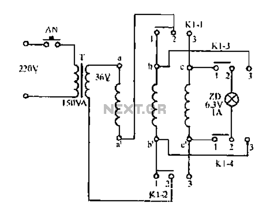
Figure aa, bb, and ce represent three-phase windings. A double throw switch Kl-1 to Kl-4 is positioned on the left side, connecting phases 1 and 2. At this point, aa and bb are in series with the secondary of...
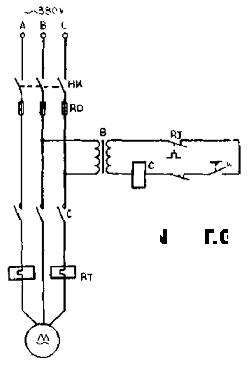
The gear lathe is unloaded from the stop line as depicted in the figure. When the turning clutch is in the stop position, the limit switch XWK is disengaged, which immediately powers the AC contactor coil C to stop...