
pic16f84a relay control board
The circuit design for the relay control board utilizes the PIC16F84A microcontroller, which serves as the central processing unit. The microcontroller's I/O ports are configured to manage both the input from control buttons and the output to the relays. The circuit includes a power supply capable of delivering the necessary voltage and current to the PIC and the relays, ensuring stable operation.
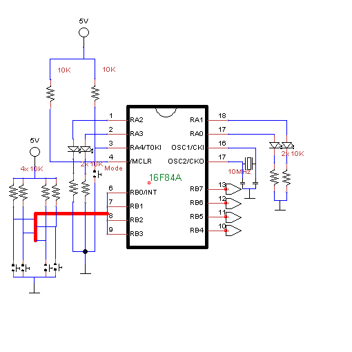
The connection of the relays to the microcontroller is critical. Each relay is connected to the output ports RB4 to RB7, which are configured as digital outputs. The relays themselves can be either normally open (NO) or normally closed (NC), depending on the application. The control buttons connected to RB0 to RB3 are used to initiate the switching or toggling actions. A debounce circuit or routine is implemented in the software to prevent erroneous multiple triggers from a single button press, enhancing the reliability of the control system.
The Mode Button on RA4 allows the user to access a settings menu, where the current configuration of the relays can be viewed and modified. The status of each relay is visually indicated by the corresponding LEDs connected to RA0 to RA3. This feedback mechanism is essential for user interaction, providing real-time status updates on the relay operations.
The EEPROM functionality is integrated into the design to ensure that the settings persist even when the power is turned off. This is achieved through specific read and write routines that interact with the microcontroller's internal EEPROM. The use of EEPROM allows for the storage of the relay states and configurations, making the system user-friendly and efficient.
Overall, the relay control board design combines hardware and software elements to create a versatile control system, suitable for various applications, including home automation and remote control solutions. The choice of components, circuit layout, and programming practices all contribute to the effectiveness and reliability of the final product.It was one of those days that you should learn some chemistry, philosophy and literature. So I thought something like what am I going to do today I started a project I did want to make for a longer time, but for what I never could find the time and concentration. I wanted to make a relay control board. That`s something like when you push on a button, an electronic switch switches on (or off, if it was on) and when you push again, it switches back. I`ll refer to this option as the switch option. It is useful when building a remote control for the lamps in your room or something like that. There`s another version of the relay control board, in which the following happens when pushing a button: the relay switches on for a second or so and then switches back.
I`ll call this option the toggle option. It`s useful when building a remote control for your computer or so. Now I`d like to have a control board with both possibilities. Therefore, I had to make something like a Mode Function, where the user could say which relay had to switch and which one had to toggle. Also, these options should be saved, also when the power would be low, or the board was disconnected from power.
With these requirements I started to build. I used a PIC16F84A, a 20MHz PIC with 64 bytes data EEPROM, which I would use to save the settings of each relay. I used the ports RB0 to RB3 as inputs. The ports RB4-RB7 were outputs, the relays were connected to those pins. If there was an input on RB0, RB7 would switch or toggle, if there was an input on RB1, RB6 would switch or toggle and so on.
I used RA4 as an input for a Mode Button, with what I could go to a settings menu. In the settings menu, LED`s on RA0 to RA3 would indicate which setting the relay had (if the LED was on, the relay would toggle. If the LED was off, the relay would switch. ) Now the code. I decided to write my code in Assembly. I don`t master C, but I could have written it in Jal. However, this would be a tiny code Jal would make the PIC slow. Also, I had never done a thing with EEPROM, not to mention the internal EEPROM of a chip. In the datasheet were two code examples, in which Microchip showed how to read or write data from or to the EEPROM.
Set inputs & outputs PORTB on, 1s delay, PORTB off ; to make sure the PIC is alive PORTA on, 1s delay, PORTB off Label Mainloop If pushed on Mode Button: Label Modeloop Get settings, settings to PORTA If mode button: Go to Mainloop If button 1: Change setting relay 1 (same for other buttons) Go to Modeloop If pushed on button 1: Get setting If switch: Get situation (on or off) Switch situation If toggle: Relay on, 1s delay Relay off (same for other buttons) Go to Mainloop list p=16F84A ; list directive to define processor #include
04s, to ensure a button was pushed and it wasn`t a rebounce of an earlier push. Here are the codes: (note that d1, d2 and d3 are temporary registers, only used in the delay routines) rebounce movlw 0x1E movwf d1 movlw 0x4F movwf d2 rebounce_0 decfsz d1, f goto $+2 decfsz d2, f goto rebounce_0 goto $+1 nop return delay1s movlw 0x15 movwf d1 movlw 0x74 movwf d2 movlw 0x06 movwf d3 delay1s_0 decfsz d1, f goto $+2 decfsz d2, f goto $+2 decfsz d3, f goto delay1s_0 goto $+1 goto $+1 return EEPROM_READ ; read EEPROM data in byte EEADR BSF STATUS, RP0 ; bank 1 BSF EECON1, RD ; EE Read BCF STATUS, RP0 ; bank 0 MOVF EEDATA, W ; set EEDATA in (W) RETURN EEPROM_WRITE ; write (W) to EEADR MOVWF EEDATA BSF STATUS, RP0 ; bank 1 BSF EECON1, WREN ; enable write MOVLW 055h MOVWF EECON2 ; write 55h MOVLW 0AAh MOVWF EECON2 ; write AAh BSF EECON1, WR ; begin write BCF STATUS, RP0 RETURN main CLRF INTCON ; all interrupts off BSF STATUS, RP0 MOVLW 0x0f MOVWF TRISB ; set in-&outputs MOVLW 0x10 MOVWF TRISA ; idem BCF STATUS, RP0 CLRF PORTA CLRF PORTB CLRF PORTBTEMP testloop ; check if the PIC is alive MOVLW 0xf0 MOVWF PORTB CALL delay1s CLRF PORTB MOVLW 0x0f MOVWF PORTA CALL delay1s CLRF PORTA mainloop BTFSS PORTA, 4 ; mode button CALL mode CLRF EEADR ; after a mode, the TEMP register should ; be reloaded CALL EEPROM_READ MOVWF TEMP BTFSS PORTB, 0 ; test input buttons CALL input0 BTFSS PORTB, 1 CALL input1 BTFSS PORTB, 2 CALL input2 BTFSS PORTB, 3 CALL input3 GOTO mainloop input0 CALL rebounce ; was it really an input. BTFSC PORTB, 0 RETURN input0l BTFSS PORTB, 0 ; wait for releasing of the button GOTO input0l CALL rebounce BTFSS PORTB, 0 GOTO input0l BTFSS TEMP, 0 ; toggle or switch GOTO switchoutput0 GOTO toggleoutput0 input1 CALL rebounce ; for comments, see label input0 BTFSC PORTB, 1 RETURN input1l BTFSS PORTB, 1 GOTO input1l CALL rebounce BTFSS PORTB, 1 GOTO input1l BTFSS TEMP, 1 GOTO switchoutput1 GOTO toggleoutput1 input2 CALL rebounce ; for comments, see label input0 BTFSC PORTB, 2 RETURN input2l BTFSS PORTB, 2 GOTO input2l CALL rebounce BTFSS PORTB, 2 GOTO input2l BTFSS TEMP, 2 GOTO switchoutput2 GOTO toggleoutput2 input3 CALL rebounce ; for comments, see label input0 BTFSC PORTB, 3 RETURN input3l BTFSS PORTB, 3 GOTO input3l CALL rebounce BTFSS PORTB, 3 GOTO input3l BTFSS TEMP, 3 GOTO switchoutput3 GOTO toggleoutput3 switchoutput0 ; check status, set on or off relay BTFSC PORTBTEMP, 7 GOTO output7off BSF PORTB, 7 BSF PORTBTEMP, 7 RETURN output7off BCF PORTB, 7 BCF PORTBTEMP, 7 RETURN switchoutput1 ; idem BTFSC PORTBTEMP, 6 GOTO output6off BSF PORTB, 6 BSF PORTBTEMP, 6 RETURN output6off BCF PORTB, 6 BCF PORTBTEMP, 6 RETURN switchoutput2 ; idem BTFSC PORTBTEMP, 5 GOTO output5off BSF PORTB, 5 BSF PORTBTEMP, 5 RETURN output5off BCF PORTB, 5 BCF PORTBTEMP, 5 RETURN switchoutput3 ; idem BTFSC PORTBTEMP, 4 GOTO output4off BSF PORTB, 4 BSF PORTBTEMP, 4 RETURN output4off BCF PORTB, 4 BCF PORTBTEMP, 4 RETURN toggleoutput0 BSF PORTB, 7 ; toggle relay CALL delay1s BCF PORTB, 7 RETURN toggleoutput1 ; idem BSF PORTB, 6 CALL delay1s BCF PORTB, 6 RETURN toggleoutput2 ; idem BSF PORTB, 5 CALL delay1s BCF PORTB, 5 RETURN toggleoutput3 ; idem BSF PORTB, 4 CALL delay1s BCF PORTB, 4 RETURN ;* mode CALL rebounce ; was it really an input BTFSC PORTA, 4 RETURN modecl BTFSS PORTA, 4 ; wait for release of button GOTO modecl CALL rebounce BTFSS PORTA, 4 GOTO modecl modear CLRF EEADR ; mode label, after rebounce CALL EEPROM_READ ANDLW 0x0f MOVWF TEMP ; settings to temp MOVLW 0x0f MOVWF PORTA BTFSS TEMP, 3 ; settings to PORTA BCF PORTA, 3 BTFSS TEMP, 2 BCF PORTA, 2 BTFSS TEMP, 1 BCF PORTA, 1 BTFSS TEMP, 0 BCF PORTA, 0 modeloop BTFSS PORTB, 0 ; check input buttons GOTO modetoggle0 BTFSS PORTB, 1 GOTO modetoggle1 BTFSS PORTB, 2 GOTO modetoggle2 BTFSS PORTB, 3 GOTO modetoggle3 BTFSS PORTA, 4 ; check mode button GOTO togglemode GOTO modeloop modetoggle0 ; change setting CALL rebounce BTFSC PORTB, 0 GOTO modeloop mt0cl BTFSS PORTB, 0 GOTO mt0cl CALL rebounce BTFSS PORTB, 0 GOTO mt0cl BTFSS TEMP, 0 ; mode on or off GOTO mode0on GOTO mode0off modetoggle1 ; for comments, see label modetoggle0 CALL rebounce BTFSC PORTB, 1 GOTO modeloop mt1cl BTFSS PORTB, 1 GOTO mt1cl CALL rebounce BTFSS PORTB, 1 GOTO mt1cl BTFSS TEMP, 1 GOTO mode1on GOTO mode1off modetoggle2 ; for comments, see label modetoggle0 CALL rebounce BTFSC PORTB, 2 GOTO modeloop mt2cl BTFSS PORTB, 2 GOTO mt2cl CALL rebounce BTFSS PORTB, 2 GOTO mt2cl BTFSS TEMP, 2 GOTO mode2on GOTO mode2off modetoggle3 ; for comments, see label modetoggle0 CALL rebounce BTFSC PORTB, 3 GOTO modeloop mt3cl BTFSS PORTB, 3 GOTO mt3cl CALL rebounce BTFSS PORTB, 3 GOTO mt3cl BTFSS TEMP, 3 GOTO mode3on GOTO mode3off togglemode ; get out of mode modus CALL rebounce ; was it really an input BTFSC PORTA, 4 GOTO modeloop tmcl BTFSS PORTA, 4 GOTO tmcl CALL rebounce BTFSS PORTA, 4 GOTO tmcl CLRF PORTA RETURN mode0on BSF TEMP, 0 ; put toggle on in settings MOVF TEMP, W CLRF EEADR CALL EEPROM_WRITE GOTO modear mode0off BCF TEMP, 0 ; put toggle off in settings MOVF TEMP, W CLRF EEADR CALL EEPROM_WRITE GOTO modear mode1on BSF TEMP, 1 ; see mode0on MOVF TEMP, W CLRF EEADR CALL EEPROM_WRITE GOTO modear mode1off BCF TEMP, 1 ; see mode0off MOVF TEMP, W CLRF EEADR CALL EEPROM_WRITE GOTO modear mode2on BSF TEMP, 2 ; see mode0on MOVF TEMP, W CLRF EEADR CALL EEPROM_WRITE GOTO modear mode2off BCF TEMP, 2 ; see mode0off MOVF TEMP, W CLRF EEADR CALL EEPROM_WRITE GOTO modear mode3on BSF TEMP, 3 ; see mode0on MOVF TEMP, W CLRF EEADR CALL EEPROM_WRITE GOTO modear mode3off BCF TEMP, 3 ; see mode0off MOVF TEMP, W CLRF EEADR CALL EEPROM_WRITE GOTO modear
🔗 External reference
Related Circuits
Automatic door control systems typically have a high market price for finished products. The proposed method is suitable for home use, utilizing easily accessible components. This design is ideal for those interested in creating their own automatic door system....
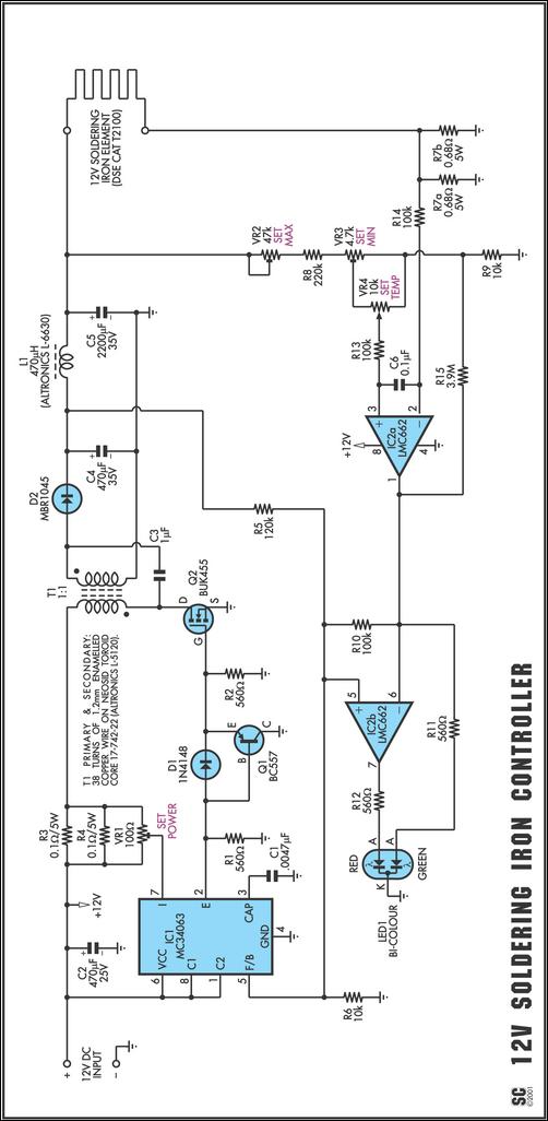
One reason commercial soldering stations are costly is that they typically use soldering irons equipped with built-in temperature sensors, like thermocouples. This circuit design eliminates the necessity for a specialized sensor by directly sensing the temperature of a soldering...
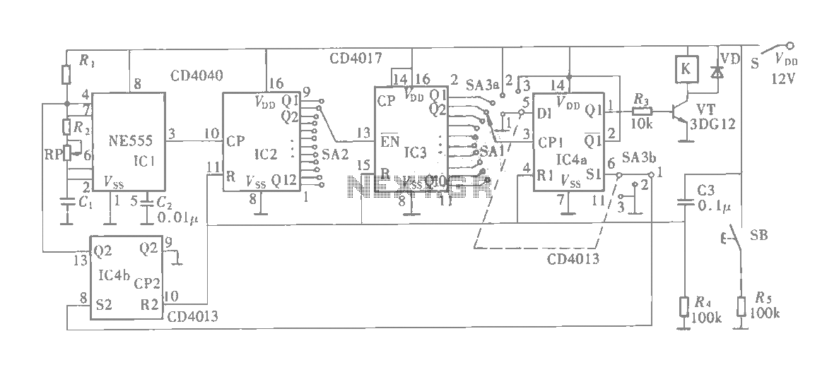
The multifunction circuit primarily refers to its capability to operate in three modes: "delayed pull," "time release," and "delayed cycle." The term "delay" indicates that the relay is energized after a predetermined time; however, the relay does not activate...
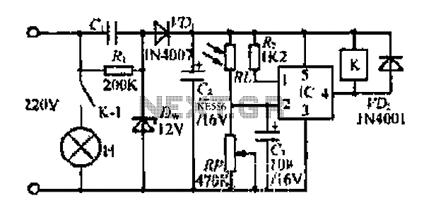
At dawn, light illuminates the photosensitive resistor RL, causing its resistance to decrease. This switch IC (2) exhibits a high electrical footprint. When light is present, the relay K does not activate. At night, in the absence of light,...
Motor control, energy efficiency of inverter (AC drive) selection, and parameters setting guidance in the mining industry: vector control, open loop or closed loop control, with energy braking unit or energy feedback unit. In the context of motor control for...
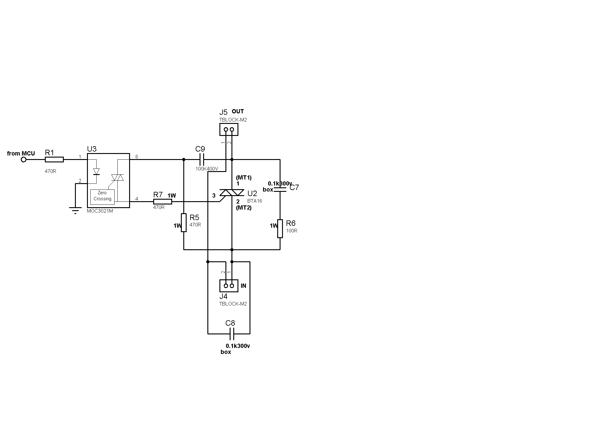
Sufficient snubbering appears to be present around the TRIAC, which should mitigate DV/DT-based switching, preventing the TRIAC from inadvertently turning on due to noise on the gate lead. The issue likely resides on the microcontroller side. When the microcontroller...