
Electronic Tachometer
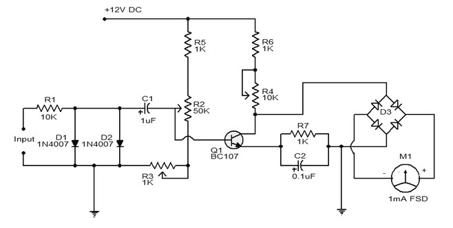
The tachometer circuit operates by receiving an input signal, typically in the form of pulses generated by a rotating object. The frequency converter circuit is designed to convert this input frequency into a corresponding current. This is achieved through the use of components such as resistors, capacitors, and operational amplifiers that work together to create a linear relationship between the input frequency and the output current.
The output current is then directed to a milliammeter, which serves as the display element of the tachometer. The milliammeter is calibrated to show the frequency of the input signal directly, allowing for easy reading and interpretation of the rotational speed. The deflection of the milliammeter needle correlates with the frequency, providing a visual representation of the speed of the rotating object.
To enhance the accuracy and responsiveness of the tachometer, additional features may be incorporated, such as filtering circuits to eliminate noise from the input signal and voltage regulation to ensure stable operation. The design may also include a zero adjustment mechanism to calibrate the device before use, ensuring that the readings are precise and reliable.
In summary, this simple tachometer schematic effectively demonstrates the conversion of input frequency into a proportional current, which is then displayed on a milliammeter, providing a straightforward yet effective means of measuring rotational speed.Here is a simple Tachometer schematic. The basis of the frequency converter circuit-current, which converts the input signal into a proportional current measured pointer device. Deflection milliammeter proportion to the frequency input sign. 🔗 External reference
Related Circuits

A diode, such as the IN4148, has a typical temperature coefficient of -2 mV/°C at a 1 mA diode current. Transistors Q1 and Q2 form a constant current source. Diode D1 serves as the temperature sensor. Integrated circuits ICl-a...
A fast electronic fuse designed to operate on 230V AC with an adjustable trip current. When the current through the load exceeds a level determined by the position of the wiper on the 1k wire-wound pot, this circuit cuts...

The EM4294 is an analog front end designed for high-security 13.56 MHz RFID reader systems. This reader integrates the cryptographic algorithm of the EM4035 transponder IC, which is associated with four secret keys. Each secret key has a length...

The electronic switch functions as a multifunctional preamplifier. It features a five-way touch electronic switch, a high-speed DC servo RIAA ultralow distortion amplifier, and can control volume, tone, and power amplifier electrical path phase. The TC9152, shown in Figure...
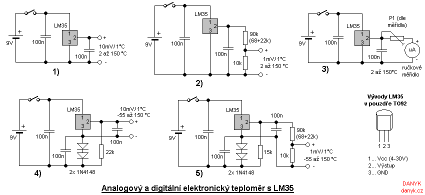
The electronic thermometer has numerous applications. Standard mercury thermometers cannot be used everywhere due to their size, fragility, or the need for remote measurement. The advantages of electronic thermometers include their compact size, low heat capacity of probes, faster...
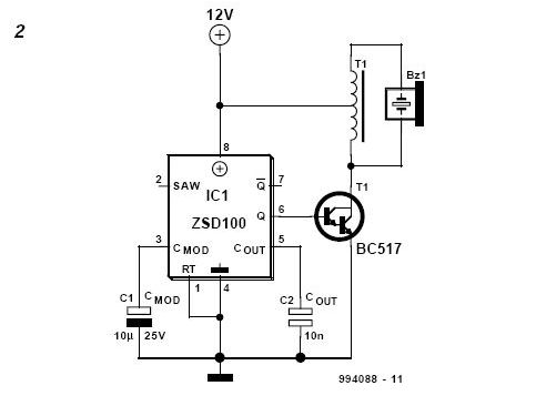
The DIY Electronic Siren circuit described here can produce three distinct US-style siren sounds: DIY police, DIY ambulance, and fire engine. The desired sound can be selected using switch S1. This circuit is suitable for use in toys (such...