
Electronic thermometer(2)
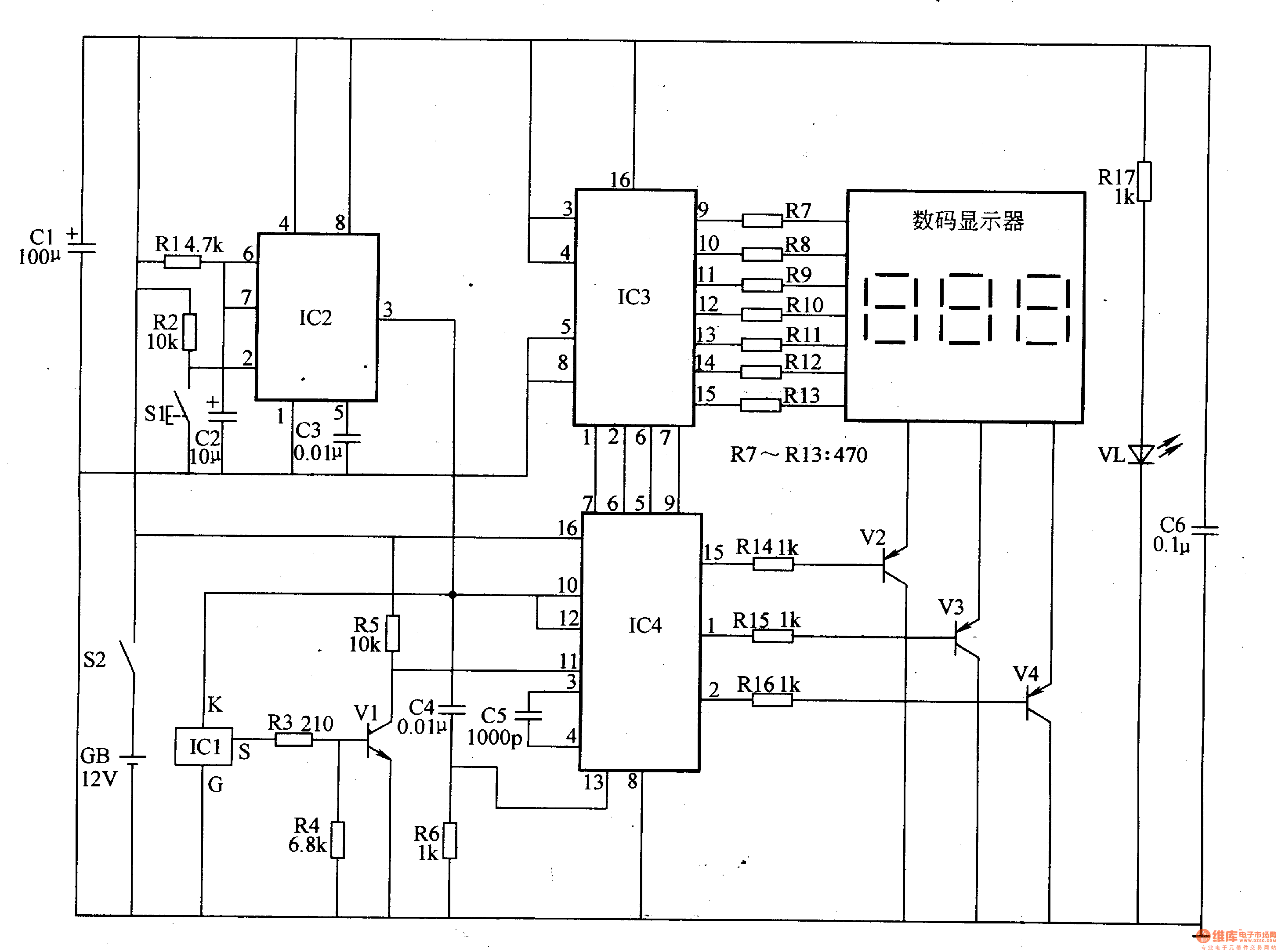
The electronic thermometer is designed to accurately measure temperatures within the range of 0 to 50 degrees Celsius, making it suitable for various applications such as laboratory experiments, food safety, and environmental monitoring. The precision of 0.1 degrees Celsius ensures that the readings are reliable and suitable for sensitive measurements.
The temperature detection circuit typically utilizes a temperature sensor, such as a thermistor or a digital temperature sensor like the DS18B20, which converts the temperature into an electrical signal. This signal is then processed by the monostable circuit, which may serve to stabilize the output signal and ensure that the readings are consistent over time.
The digital display drive circuit is responsible for converting the processed signal into a format that can be displayed on a digital screen, usually a seven-segment display or an LCD. This circuit interfaces with the microcontroller or a dedicated driver IC to facilitate the display of temperature readings in real-time.
The power supply circuit provides the necessary voltage and current to the entire system, ensuring that all components function correctly. This circuit may include voltage regulators, capacitors for smoothing, and possibly a battery management system if the thermometer is designed for portable use.
Overall, this electronic thermometer circuit combines multiple components to deliver accurate temperature readings, with a user-friendly digital display that enhances usability in various settings.The temperature measuring range of this electronic thermometer is 0-50?, the precision is 0.1?, the measurement results are intuitively displayed by digital display. This electronic thermometer circuit is composed of temperature detection circuit, monostable circuit, digital display drive circuit and power supply circu..
🔗 External reference
Related Circuits

Embedded system design engineers create examples of their work from the 1990s era. Embedded systems have evolved significantly since the 1990s, and the design work from that period reflects the technological limitations and innovations of the time. Engineers in this...
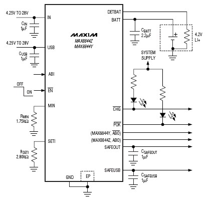
The MAX8844 lithium-ion charger integrated circuit (IC) from Maxim Semiconductors facilitates the design of a simple and efficient charger circuit for a single-cell lithium-ion battery. This charger integrates a current-sense circuit, a MOSFET pass element, thermal-regulation circuitry, and eliminates...

The mechanical and electrical schematic in Figure 5 illustrates a simple circuit comprising several components. The first component is an electronic crossover section utilizing the NE5532 operational amplifier, which is known as the "Emperor of the op-amp." This section...

The electronic dog repellent circuit diagram below features a high-output ultrasonic transmitter designed primarily to function as a repeller for dogs and cats. The electronic dog repellent circuit utilizes an ultrasonic transmitter to emit sound waves at frequencies above the...

This is an electronic siren circuit diagram. The sound produced imitates the rise and fall of an American police siren. When first switched on, the 10µF capacitors are discharged, and both transistors are off. When the push-button switch is...

An electronic decorative peacock consists of 10 light-emitting diodes (LEDs), each of which contains multiple LEDs arranged in the tail of the peacock model. The light emission drive circuit operates the fan-shaped LEDs in a cyclic manner, emitting light...