
Electronic dog repellent project
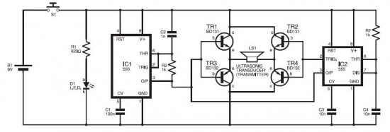
The electronic dog repellent circuit utilizes an ultrasonic transmitter to emit sound waves at frequencies above the audible range for humans, typically around 20 kHz to 40 kHz. This frequency is unpleasant for dogs and cats, effectively deterring them from approaching the area where the device is deployed.
The circuit generally consists of several key components: a power supply, an oscillator circuit, a modulator, and a piezoelectric ultrasonic transducer. The power supply can be a battery or a wall adapter, providing the necessary voltage and current for the circuit operation.
The oscillator circuit generates a high-frequency signal, which is then modulated to create varying sound patterns that enhance the repelling effect. This modulation can be achieved using a simple transistor-based oscillator or a more complex microcontroller setup that allows for programmable frequency variations.
The piezoelectric ultrasonic transducer converts the electrical signals from the oscillator into ultrasonic sound waves. The design of the transducer is crucial, as it determines the efficiency and range of the emitted sound.
For optimal performance, the circuit may include additional features such as a motion sensor to activate the ultrasonic transmitter only when animals are detected, thereby conserving power and extending the device's operational life.
In summary, this electronic dog repellent circuit is an effective solution for deterring unwanted animals using high-frequency sound waves, leveraging key electronic components to achieve its purpose.The electronic dog repellent circuit diagram below is a high output ultrasonic transmitter which is primarily intended to act as a dog and cat repeller, wh. 🔗 External reference
Related Circuits
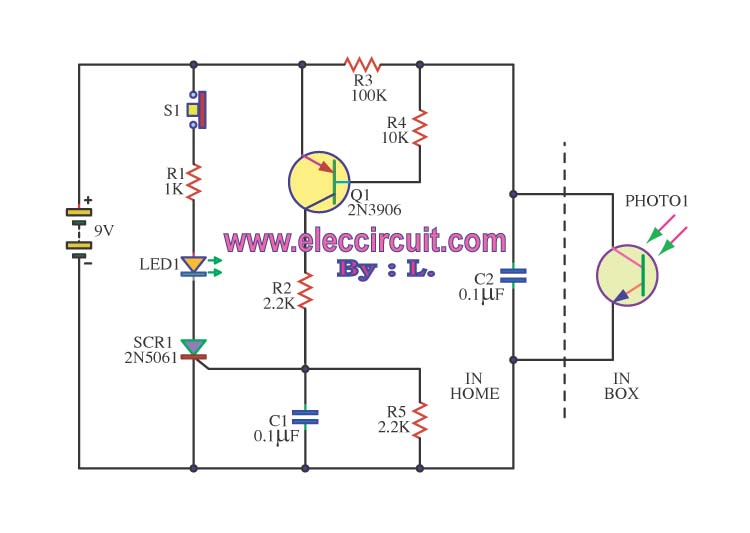
This is an integrated electronic mailbox circuit diagram designed for a front door. It activates when the door is opened. Additionally, when the cabinet photo detector is exposed to light, it will... The integrated electronic mailbox circuit is designed to...
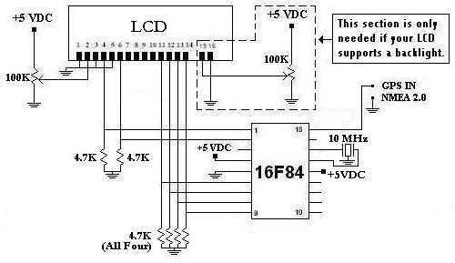
This is a project that I started back late 2003 when I just starting to learn PIC programming. I wanted to building something that actually did something useful. This project is based on a PIC16F84. I actually came up...
This modified Hartley oscillator can be utilized to attract new friends or serve as a replacement doorbell. The modified Hartley oscillator is a type of electronic oscillator that generates a continuous waveform, typically a sine wave, using an LC (inductor-capacitor)...
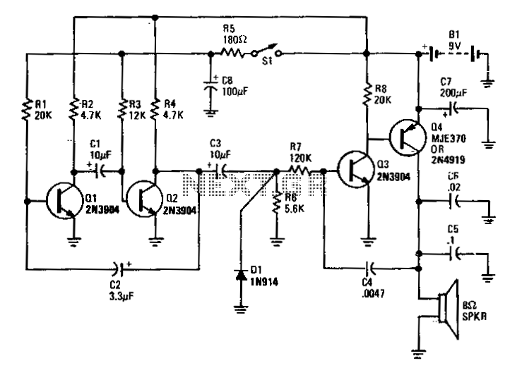
Transistors Q1 and Q2 form the two halves of a free-running multivibrator, with the frequency determined by the voltage across capacitor C8. This capacitor is charged and discharged by the operation of switch S1. Transistors Q3 and Q4 constitute...

This smoke detector electronic project is designed using the LM1801 and common electronic components. The smoke detector circuit diagram does not utilize ionization detection, gas sensors, or optocouplers; instead, it employs two photoresistors (LDRs) and an LED. The circuit...
A fast electronic fuse designed to operate on 230V AC with an adjustable trip current. When the current through the load exceeds a level determined by the user, the fuse will trip to protect the circuit. The electronic fuse functions...