
Electronic thermometer circuit
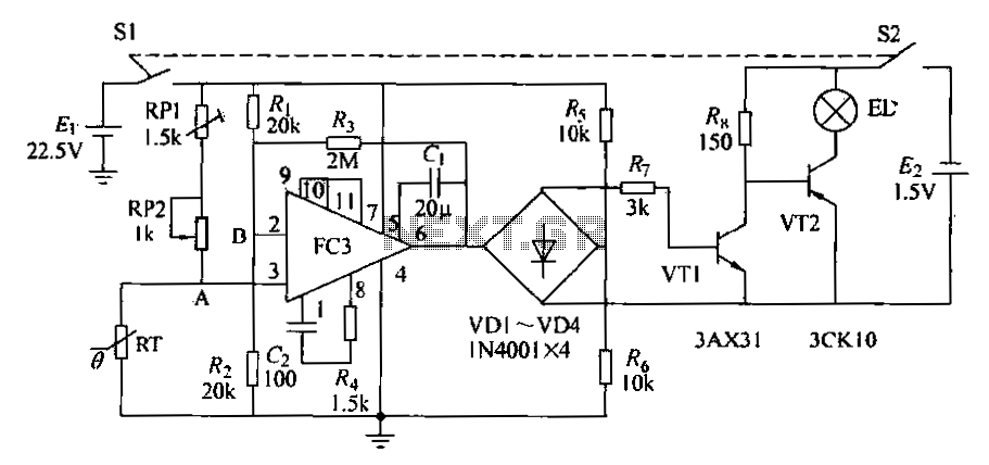
The electronic thermometer circuit operates by utilizing a thermistor, which is a temperature-sensitive resistor that changes its resistance based on temperature variations. The negative temperature coefficient (NTC) thermistor model RRG3J22 is specifically chosen for its sensitivity to temperature changes, making it ideal for precise temperature measurements. The integrated operational amplifier (A) amplifies the differential voltage signal generated between points A and B, which is crucial for accurate temperature detection.
The rectification process is accomplished through the arrangement of diodes (VD1 to VD4), which ensure that the output signal is unidirectional. This is necessary for controlling the subsequent switching action of the transistors (VT1 and VT2). The switching mechanism allows for the indication of temperature through a small light bulb. When the thermistor's resistance aligns with the set reference point, indicated by the adjustment of RP2, the circuit transitions from a non-conductive state (light bulb off) to a conductive state (light bulb on), signaling that the desired temperature has been reached.
The use of a potentiometer for scaling temperature readings allows for flexibility in calibration, enabling the circuit to be tailored for specific temperature ranges. The operational amplifier's performance is critical; therefore, its gain and leakage current specifications must be adhered to, ensuring reliable operation. The power supply, a 5V laminated battery, provides sufficient voltage for the circuit components, maintaining functionality over extended use. This design combines simplicity with effectiveness, making it a practical solution for temperature measurement applications.Electronic thermometers as shown in the circuit. RT is the thermistor, A is an integrated operational amplifier. VD1 ~ VD4 composition marked by the scribe mushroom flow channe l, unidirectional output signal. VT1, VT2 etc. switching circuit. When the thermistor RT temperature resistance with the measured object changes to a certain degree of resistance when, A, B two points there is a difference signal output of this signal by the A amplification, after VD1 ~ VD4 rectified, added to the base of VT1 pole, VT1 conduction, VT2 off, a small light bulb mouth. Does not shine this time. Changing the electrical resistance of RP2 locator, so that A, B no difference between the two output signals, the deadline VT1, VT2 conduction, small bulbs on the light.
If the mark on the temperature scale potentiometer, then the lights when reading out the measured object temperature. Rr metal shell negative temperature coefficient thermistor, model RRG3J22,20 when the resistance is lOkfl, if the glass envelope is more desirable (positive temperature coefficient thermistor may be).
A use of substandard goods gain operational amplifier. VT1, VT2 leakage current is less than lOOtjLA, Lu is greater than 30. A small light bulb voltage of 2.5V or less. Ei with ZZ. 5v Instrument laminated battery, easy bureau section 4 battery.
Related Circuits

This page features a circuit that has twenty open collector outputs that turn on one at a time in a continuous sequential manner. The circuit utilizes the 74LSxx family of TTL integrated logic devices. The circuits are designed to...

This flash circuit is a typical camera flash. This flash circuit functions as a high-voltage power supply for camera flash units, enabling the rapid discharge of energy to produce a bright flash of light. The primary components of a typical...
This project was completed successfully, achieving the desired frequency and strength. For assistance, please reach out for support in resolving any issues. The project involves the design and implementation of an electronic circuit that operates at a specified frequency and...
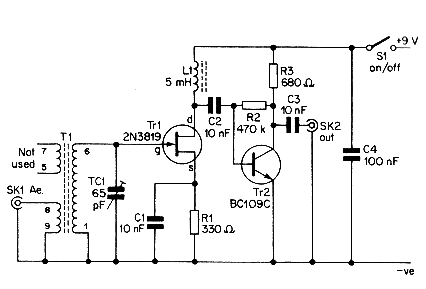
This simple aerial booster circuit design could serve as an alternative or a hobby project for creating an aerial booster device for Citizen Band (CB) radio. The aerial booster circuit is designed to enhance the performance of Citizen Band (CB)...
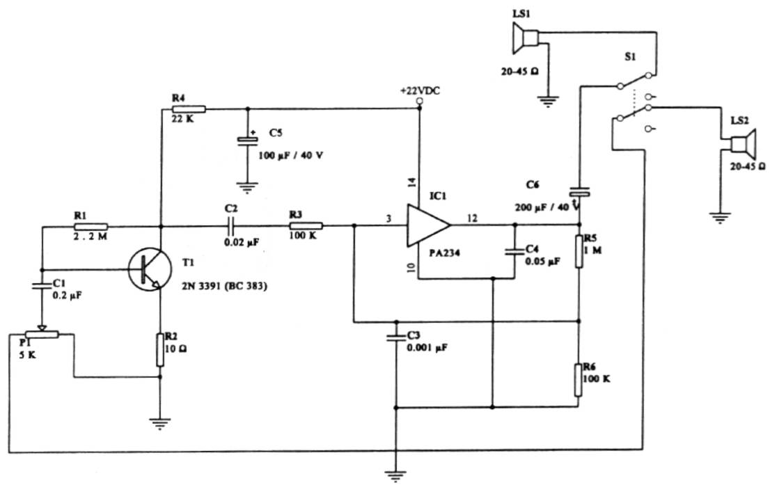
This intercom circuit is versatile and can be utilized in various applications. It operates at 22V, although it may function at a lower voltage (experimental testing is suggested). The circuit utilizes a loudspeaker with an impedance of 20-45 Ohms...

A TDA1024 electronic thermostat measures soil temperature using thermistor R6. The circuit employs zero-crossing switching to control the heater, which is constructed from elastic-coated steel wire. A potentiometer (PI) is utilized to adjust the temperature setting. The heater must...