
electronic toggle switch no1
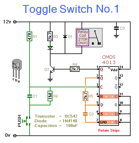
This circuit serves as a toggle switch mechanism, where a momentary push-button switch controls the state of a relay. The relay acts as an electromechanical switch that can control higher voltage or current loads, making this design suitable for various applications, such as home automation or industrial control systems.
The circuit utilizes a single half of the CMOS 4013 dual D flip-flop IC, which is key to achieving the toggle functionality. When the button is pressed, it sends a pulse to the flip-flop, changing its output state. The output from the flip-flop is connected to the relay coil, which energizes the relay when the output is high. A second press of the button sends another pulse, reversing the output state and de-energizing the relay.
The LED indicator is connected in parallel with the relay coil, providing a visual cue that the relay is active. The LED will illuminate when the relay is energized, offering a straightforward way to confirm the relay's status without needing to measure voltages or currents directly.
When designing the circuit, it is crucial to select components that match the intended operating voltage. The relay must have a coil voltage rating that corresponds to the power supply voltage, which can range from 5V to 15V, allowing flexibility in applications.
It is also important to note the safety precautions regarding the use of the relay. The onboard relay is not suitable for switching mains voltage due to the proximity of low-voltage components, which could lead to dangerous situations. For applications involving higher voltages, an external relay rated for the required voltage should be used, and it should be mounted in a safe location away from the main circuit board to ensure adequate isolation and safety.This simple circuit will energize and de-energize a relay at the push of a button. Any type of momentary action push-to-make switch can be used. Pushing the button once - will energize the relay. And pushing it a second time - will de-energize the relay. I`ve drawn the circuit with a single pole relay. But you can use a multi-pole relay if it suit s your application. Only one half of the Cmos 4013 is used. So you could construct two independent toggle switches with a single IC. The circuit will work at anything from 5 to 15-volts. All you need do is select a relay with a coil voltage that suits your supply. The LED provides a visual indication that the relay is energized. In effect - it tells you whether the switch is on or off. It`s not necessary to the operation of the circuit. If you wish you may leave out R3 and the LED. Do not use the "on-board" relay to switch mains voltage. The board`s layout does not offer sufficient isolation between the relay contacts and the low-voltage components. If you want to switch mains voltage - mount a suitably rated relay somewhere safe - Away From The Board.
🔗 External reference
Related Circuits

Stethoscopes are not only useful for doctors, but home mechanics, exterminators, spying and any number of other uses. Standard stethoscopes provide no amplification which limits their use. This circuit uses op-amps to greatly amplify a standard stethoscope, and includes...
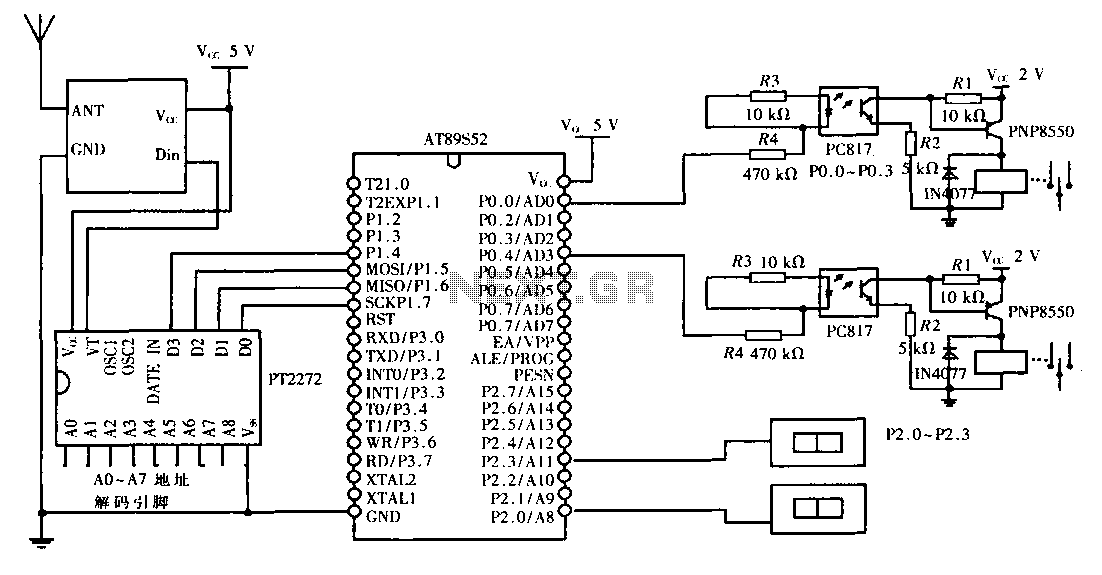
This design aims to create a long-distance wireless remote control switch lighting control system, which consists of a transmission system and a reception system. The system utilizes wireless transceiver modules for RF transmission and reception. The transmitting portion mainly...

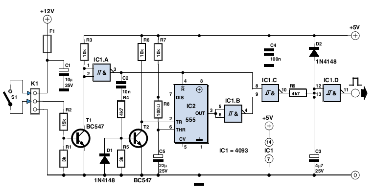
This time delay switch circuit is designed to activate an AC load, such as lamps, after a delay of three minutes. It helps protect the load from inrush currents and transients during power-on, which can potentially harm the device....

A, B, and C are used for a high-power split-phase system. The A + B' C' arrangement serves as a phase line for a range generator. The A-A' indole path string includes two 220V / 15W bulbs, which are...
The circuit described here was designed as an addition to a remotely controlled garage door opener. The problem was that a brief burst of interference, arising from a thunderstorm or a mains spike, was enough to trigger the mechanism,...
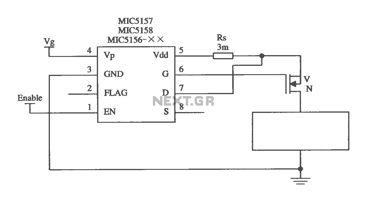
The MIC5156 is a device that incorporates a current limiting function, allowing it to handle high output currents. It can operate with or without a switching regulator circuit. The S terminal is left vacant, and a 16V Zener diode...