
Intelligent home lighting control switch transmitter and receiver circuit
The wireless remote control switch lighting control system is engineered to operate effectively over long distances, making it suitable for a variety of applications in smart home environments. The transmission system is designed around the PT2262 chip, which is critical for encoding the control signals. This chip facilitates the transmission of signals over a frequency of 315 MHz, ensuring robust communication between the transmitter and receiver.
In the transmitter circuit, the addressing key circuit allows the user to select which channel to activate. Each of the four channels is independently controlled through the dedicated buttons connected to the data input terminals D0 to D3. The encoding process occurs when a button is pressed, sending a high voltage signal to the corresponding data terminal, which the PT2262 then encodes into a unique signal based on the predefined address and data inputs.
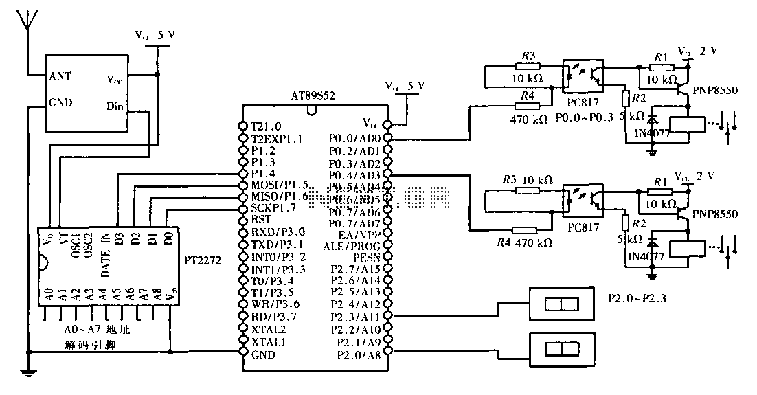
The receiving system is equally sophisticated, utilizing the AT89S52 microcontroller, which processes the incoming signals and controls the load circuit. This microcontroller can be programmed to respond to the specific encoded signals received from the transmitter, allowing for versatile control over various lighting devices. The load circuit is designed to handle the power requirements of the connected lighting systems while maintaining safety and efficiency.
Power supply considerations are paramount in this design. The transmitter operates on a single 12 V battery, while the receiver uses three 1.5 V batteries, ensuring that both systems are energy-efficient. The AT89S52 microcontroller requires a stable 5 V DC power supply, which can be achieved through a voltage regulator or a dedicated power supply module.
Overall, this wireless remote control switch lighting control system exemplifies modern electronic design principles, offering a scalable, efficient, and user-friendly solution for intelligent home lighting management. The combination of advanced encoding techniques, microcontroller programming, and thoughtful power management results in a reliable system that enhances convenience and functionality in residential lighting control.This design is to achieve a long-distance wireless remote control switch lighting control system consists of two parts the transmission system and the reception system. The system uses wireless transceiver modules RF transmission and reception circuit, emitting portion mainly by addressing the key circuit, encoding and transmitting circuit modules; received by the receiving part of the main module, MCU control circuit and load circuit. Launch system using 1 12 V battery-powered, the receiving system using 3 1.5 V battery-powered, single-chip with 5 V DC power supply, energy-saving power supply, easy.
Wireless transmission system circuit: The main use PT2262 chip to complete the circuit of the key signal is encoded PT2262 can control four channels. Figure 2, PT2262 1 to 8 feet is coded address side, each end of the address can be set "high" (the pin is connected to 12 V), "low" (the grounding pin), "vacant" Three states.
10 to 13 feet is coded data input terminal D3 ~ D0 (using 4-bit data), in each data terminal is connected to a button to control different devices. When you press the button, the button corresponding to the voltage of 12 V is applied to the data terminal, and data terminal through the crystal information signals and transmitted.
PT2262 will be encoded according to the data set and entered the address code, coded pulse from 17 feet out. When 17 feet oscillation output pulse "0", Vl composition; wireless communication controlled by coded pulses, pulse is 17 feet when the "l", composed oscillator V1, resulting in 315 MHz high frequency signal and transmitted to stop working.
This design uses microcontroller AT89S52 and chipsets PT2262 / 2272 to achieve a programmable 4-way wireless switching system for lighting control, avoiding the use of special decoder chip restrictions, to take advantage of scalable and flexible software and hardware resources, system good, and low cost, low power consumption, is a scientific solution intelligent home lighting control.
Related Circuits
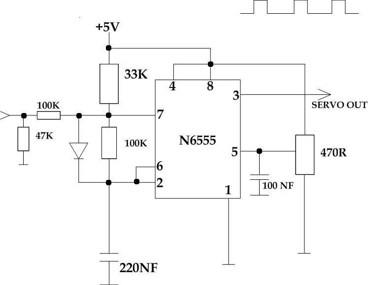
This circuit takes a standard 0-10V control voltage (for example, from an analog light control desk) and outputs a standard 1-2 ms control pulse for RC servo motors. The components used in this circuit include: - 2 x 100...
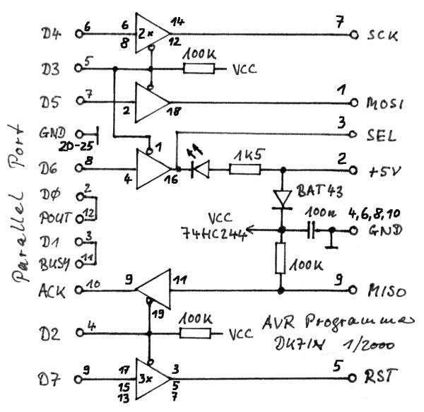
The gap between TTL (Transistor-Transistor Logic) devices and personal computers can be effectively bridged with modern microcontrollers. These microcontrollers not only incorporate a central processing unit (CPU) but also include program and data memory, EEPROM, input/output (I/O) ports, timers,...
The following governor is designed to regulate the light intensity of a 220 V incandescent lamp. The circuit consists of relatively few components, allowing for easy assembly on a small circuit board. It is recommended to enclose the completed...
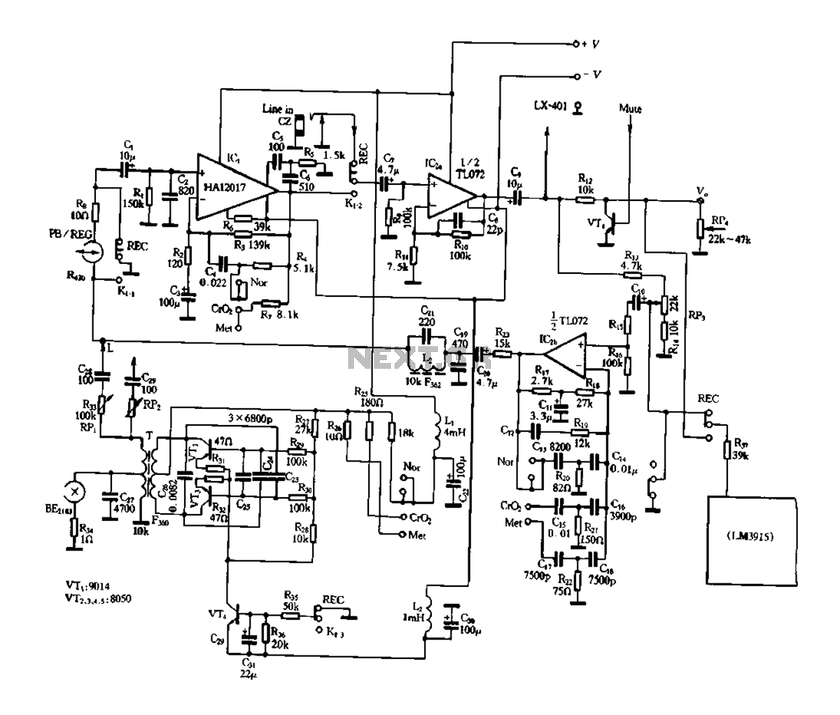
Figure 3-17 illustrates a pre-equalizer amplifier with sound recording capabilities, featuring the following characteristics: (1) The circuit does not utilize a conventional mechanical switch circuit; instead, it employs fully enclosed electromagnetic relays. This design allows for a core and...
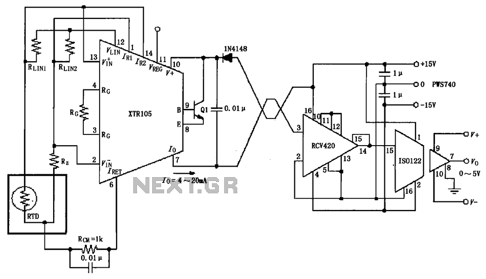
The RTD temperature sensor, as illustrated in the subsequent figure, collects temperature data from the field. This data is converted into a voltage signal by the XTR105, which is then transformed into a 4 to 20 mA current output....
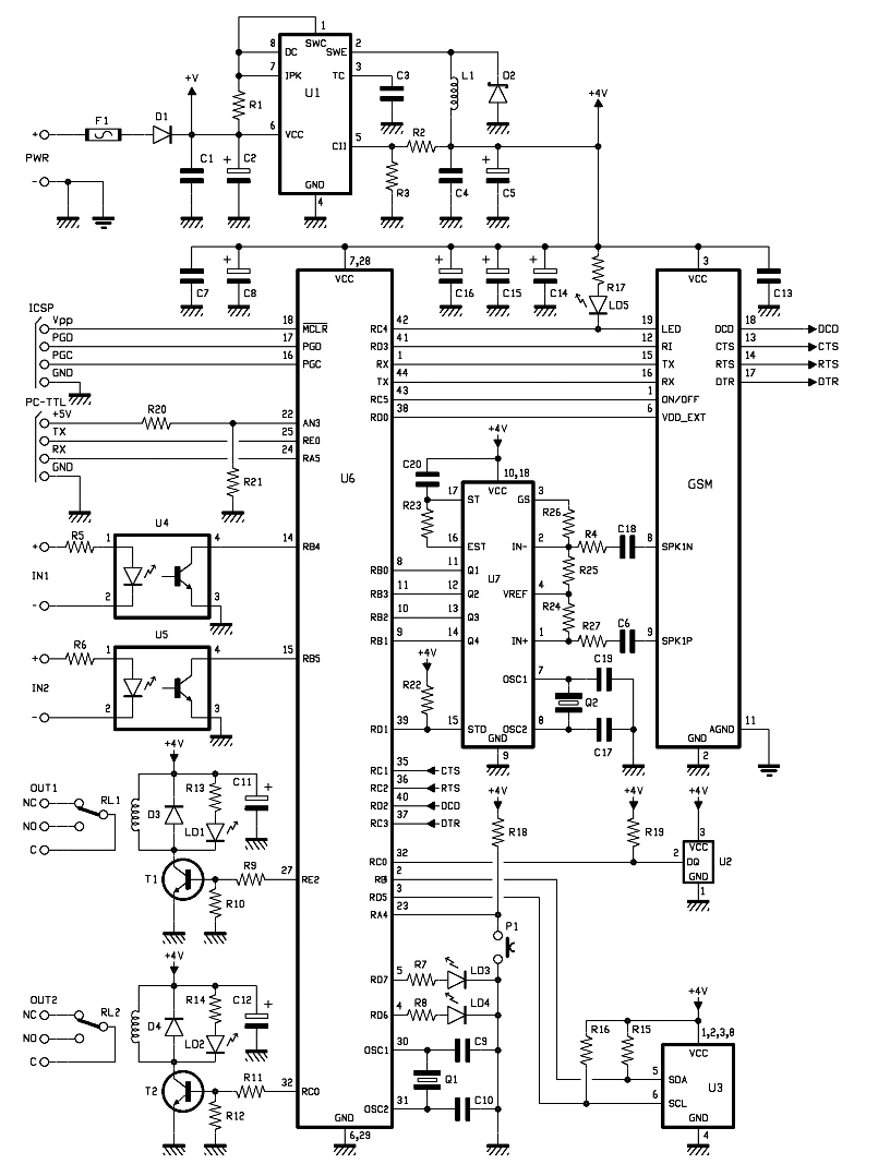
The entire remote control is managed by a PIC that oversees the GSM/GPRS module's operations, monitors room temperature via a Dallas DS1820 smart probe, controls the logical state of two opto-isolated inputs, and sends commands to two relays. Additionally,...