
Electronic VU Meter
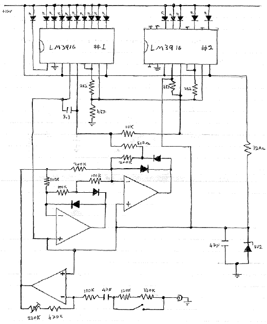
A table of audio devices lists the name, maximum output voltage, and the expected impedance for each device. This information assists in determining the sensitivity required for the meter and the necessary input impedance. The input stage includes a buffer that can provide gain or attenuation as needed while ensuring the appropriate input impedance for the source. A rectifier converts the audio input signal into a DC voltage for display purposes. The meter is connected in parallel with the load impedance being driven by the source, which results in a total impedance lower than the load impedance of the device being driven. If the total impedance is excessively low, distortion may occur due to the source attempting to drive too much current. Even with similar impedance values, the total impedance will be halved. Ideally, the input impedance of the meter should be ten times greater than the highest load impedance to minimize signal distortion and achieve a higher signal level.
The highest load impedance listed in the table is 100 kΩ for a reel-to-reel tape deck, which is infrequently used. The next highest load impedance is 50 kΩ. To determine the required input impedance for the meter, multiplying this value by ten results in 500 kΩ. When this is connected in parallel with a 50 kΩ load, the effective impedance that the source will drive is 45 kΩ. An impedance of 50 kΩ would yield an effective load of 25 kΩ. The lowest tolerable load for the sources is 10 kΩ, though this is not advisable. Therefore, a design impedance of 50 kΩ or greater will provide an adequate margin.
The output levels of the various devices differ significantly, indicating that a single reference level is insufficient. Two selectable reference levels have been established to accommodate this variability. Additionally, the frequency response of the meter must cover the Hi-Fi range of 20 Hz to 20 kHz. The meter's range will be from -20 dB to +13 dB, where -20 dB (one-tenth of the 0 dB voltage) serves as an acceptable lower threshold, and an overload level of +12 dB provides a sufficient headroom margin for peaks.
An audio millivoltmeter is one method for measuring audio frequency signals. A circuit diagram for a millivolt (mV) meter has been reviewed, featuring a moving coil meter. While this type of meter is less responsive due to the needle's movement, it is commonly utilized, albeit challenging to acquire for audio-specific purposes. The circuit comprises a three-step attenuator and a full-wave rectifier driving the moving coil meter. A notable drawback of this meter for the application is its linear scale, whereas decibel measurements are logarithmic, which may limit its effectiveness in accurately representing audio signal levels.A portable CD player, radio, cassette player, a couple of microphones and PC sound card. I am feeding these into the inputs of an audio mixer the output of which is attached to a pair of active loudspeakers. I want to be able to monitor the signal levels going in and coming out of my audio mixer to make sure that I am not overloading the next stage.
This could be a tape recorder if I were to record a CD for example. The audio mixer has four inputs each of which have a volume control. There is also a master volume control on the output amplifier. The reason for using an audio mixer is so that I do not have to swap wires around just to listen to the output from another device. I can have the output of four devices each driving an input of my mixer. I can then adjust the volume of each of the inputs so I can only hear, say, my CD player instead of my radio.
Table 1 shows some of the audio devices that I have found in the house. I have listed the name of the device, the maximum output voltage and the impedance it expects to drive. From this I can decide how sensitive hoe sensitive the meter needs to be and what the input impedance needs to be.
The input consists of a buffer that may provide any gain or attenuation needed. It also provides the required input impedance for the source. The rectifier will turn the audio input signal into a d. c. voltage to feed into the display function. The meter will be connected in parallel with the load impedance that is being driven by the source. This means that the total impedance that the source will see will be lower than the load impedance of the device that is being driven. If the total impedance is too low then distortion can occur because the source is trying to drive too much current.
Even if the impedance of the meter is similar to that of the load then the total impedance will be reduced by half. Ideally, by making the input impedance of the meter ten times greater than the highest load then any distortion on the signal being measured will be minimised and a higher signal level can be achieved.
The highest load impedance for the devices listed in Table 1 is 100 k ©. This is for the Reel to Reel Tape Deck which I rarely use, so the next biggest load impedance is 50 k ©. If I multiply this by ten to find the input impedance for the meter, it would need to be 500 k ©. With this in parallel with a 50 k ©, then the impedance that the source will be driving is 45 k ©. An impedance of 50k © would result in an effective load of 25k ©. The lowest tolerable load for the sources is 10k © but this is not recommended. This means that a design impedance of 50k © or greater will provide an adequate margin. Looking at Table 1, the output levels for the different devices are quite different, so there can not be a single reference level.
I have decided that I want two selectable reference levels, these will be: Another requirement is the range of frequencies that the meter will respond to. For this meter the frequency response needs to be the Hi-Fi range, which is 20Hz-20kHz. The range of the meter will be -20dB to +13dB. A level of -20dB (one tenth of the 0dB voltage) will provide an acceptable lower threshold, whereas an upper (overload) level of about 12dB will give a good margin of headroom for peaks.
One way of measuring audio frequency signals is to use an audio millivoltmeter. I have looked up a circuit for a millivolt (mV) meter, and it has the following characteristics: The meter uses a moving coil meter which means that it will not be quite so responsive as the needle has to move back and forth rapidly. Moving coil meters that are purpose-designed for audio use are expensive and difficult to obtain. The circuit mainly consists of a three step attenuator and a fullwave rectifier driving a moving coil meter.
A key disadvantage of this meter for my application is that it has a linear scale whereas decibels are based on a logar 🔗 External reference
Related Circuits
This project is exactly what you need. It is simple to construct and can be connected to almost any analogue multimeter. The scales are accurate over each range - certainly good enough to provide you with the value of...
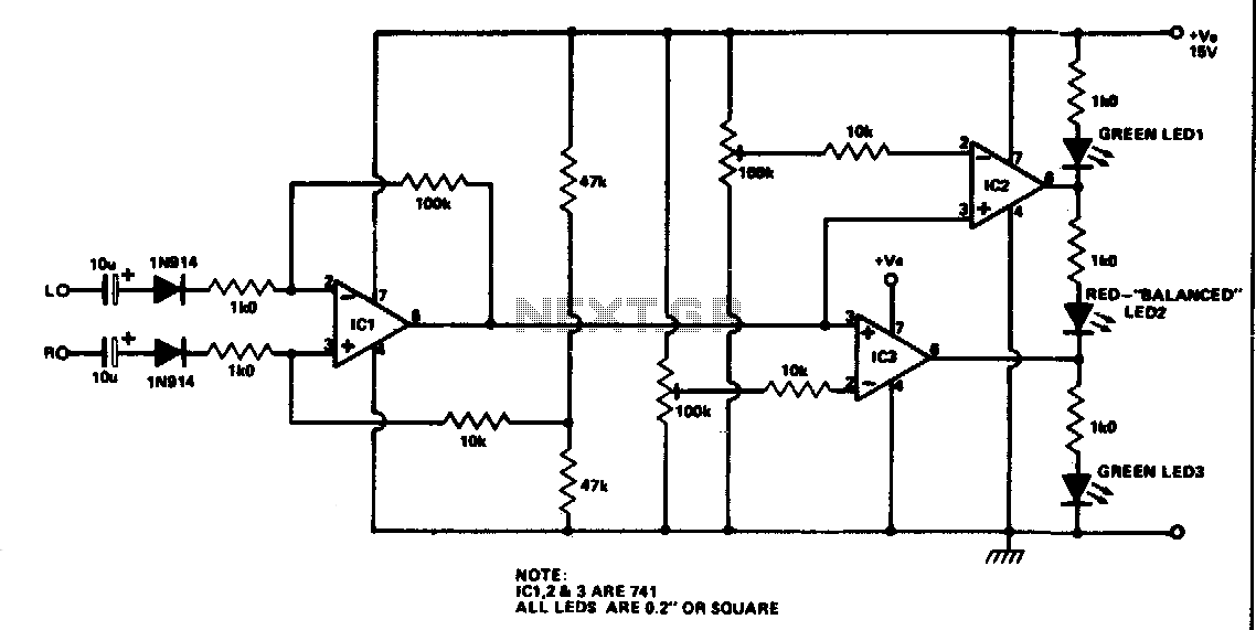
Outputs from each channel are fed to the two inputs of IC1 connected as a differential amplifier. IC2 and IC3 are driven by the output of IC1. The output of IC1 is connected to the non-inverting inputs of IC2...
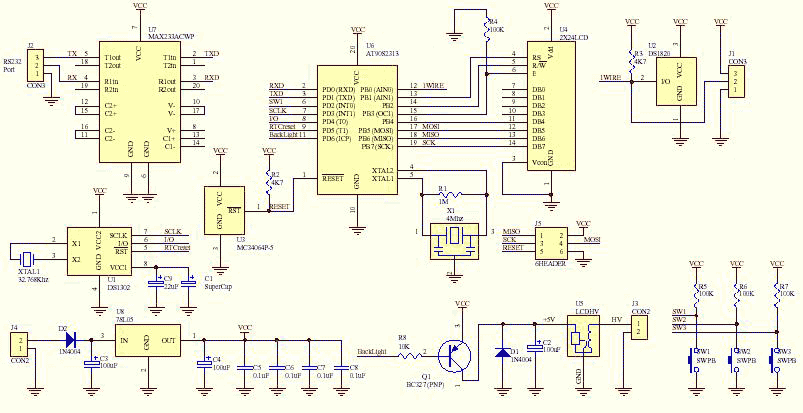
This is the fully featured, jammed packed temperature readout unit. I can measure temperature from up at 8 DS1820 digital temperature sensors all on the same 1-wire bus. That's right only 3 wires are needed to go to all...
This circuit generates a ringing sound akin to that produced by modern telephones. It comprises three nearly identical oscillators arranged in a sequence, each responsible for generating a square wave signal. The frequency of each oscillator is determined by...
The 555 timer IC is connected for Astable Operation, the clock pulses are fed to the 4017 IC via the 10K resistor. The 4017 is a 10 stage counter, output 6 (pin 5) is connected to RESET (pin 15),...
This digital DIY tachometer for bicycles utilizes two reed switches to gather speed information. The reed switches are positioned near the wheel rim, where permanent magnets are mounted on the wheel spokes. As the spokes rotate, the magnets pass...