
Emergency lighting circuit diagram
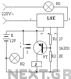
The circuit described functions as an automatic power backup system, utilizing a relay and transistors to manage the transition between power sources. The primary power source is 220V AC, which powers lamp H1 under normal operating conditions. The LSE (likely a low-voltage sensor or controller) monitors the voltage levels and provides an output signal that controls the transistor VT.
When the AC power is present, lamp H1 serves as an indicator light, signaling normal operation. The high output from the LSE keeps the transistor VT in a non-conductive state, which means that relay J remains deactivated. Consequently, lamp H2, which acts as the backup light, remains off.
During a power outage, the sudden loss of AC voltage causes lamp H1 to extinguish. The LSE detects this drop in voltage and its output signal transitions to a low state. This change turns on transistor VT, which then conducts and activates relay J. The relay, upon being energized, connects the power supply to lamp H2, causing it to illuminate automatically. This seamless transition between lamps ensures that there is minimal disruption in lighting, which is particularly important in critical situations such as surgeries.
The design of this circuit emphasizes reliability and simplicity, making it suitable for applications where continuous lighting is essential. The use of a relay provides a robust method for switching between power sources, while the transistor acts as an efficient control element, allowing for quick responses to changes in power availability. Overall, this automated system enhances safety and operational continuity during power interruptions.The device circuit works shown in Figure 11. Power outages are frequent thing, but some occasions, the power does not allow (such as the ongoing surgery, etc.). LSE with simple circuit design, fully automated. When 220V AC, the lamp H1 lights up, while the LSE feet high output, transistor VT end, the relay J is released, it does not shine direct light H2. Once a power outage, H1 off, LSE's pin output low, then transistor VT conduction, the relay J pull, turn the power lights H2, H2 light automatically convert between almost two lights interruption.
Related Circuits
This microphone preamplifier utilizes the low-noise integrated circuit (IC) uA739. The circuit serves as an example of an effective design for preamplifying dynamic microphones. The IC contains two operational amplifiers. The uA739 is a precision integrated circuit known for its...
Due to the low coupling coefficient, the primary self-inductance tends to short out the driving signal. However, utilizing a series/parallel set of capacitors for energy coupling increases the input impedance at resonance, thereby achieving good power transfer efficiency. The...

An oscilloscope front-end amplifier can be constructed using low-cost transistors and video amplifier integrated circuits (ICs). This preamplifier utilizes a FET input along with compensated attenuators, achieving an approximate bandwidth of 100 MHz, which is sufficient for most general-purpose...
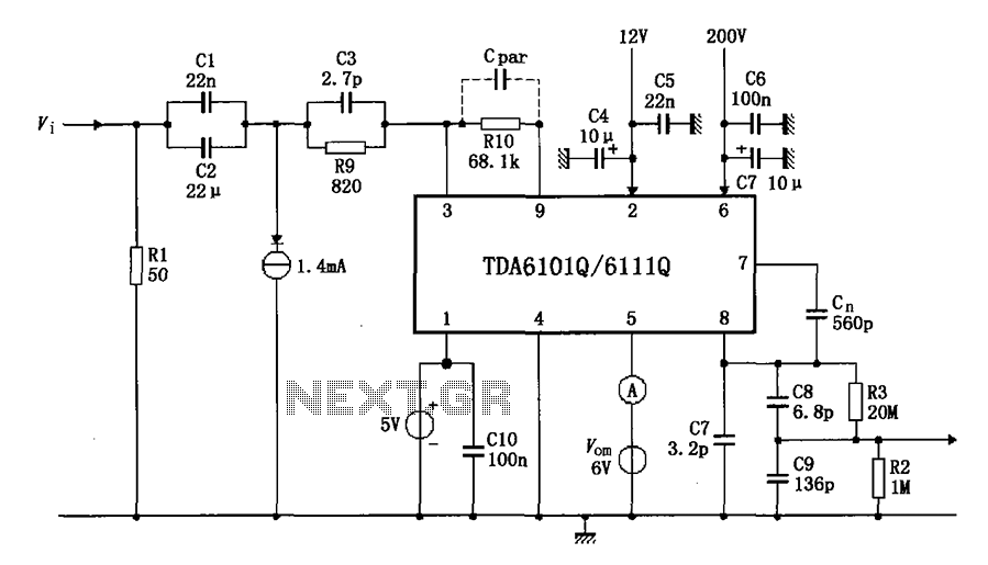
The test circuit features a feedback factor of 1/83 utilizing the DA6101Q/6111Q. The input signal is fed through a network comprising resistors R1 and R9, and capacitors C1, C2, and C3, entering the TDA6101Q, which includes three pins for...
This circuit is utilized in an impulse speed modulation system. In this system, the transmitter alters the impulse speed of the modulated beam in an optical fiber, allowing it to vary around a center frequency of 50 kHz. The...
This circuit responds to the presence of any conductive object, including humans. It does not detect object movement but can function as a proximity sensor. The circuit operates on the principle of capacitive sensing, utilizing a capacitor to detect changes...