
Enhanced 5 Digit Alarm Keypad

The Modular Burglar Alarm circuit employs a sophisticated method of user authentication through a keypad interface, integrating a series of components that work together seamlessly to provide a reliable security solution. At the core of the system is the CMOS 4081 quad 2-input AND gate, which is pivotal in determining the validity of the entered code. The design allows for flexibility in code selection, accommodating both numeric and non-numeric symbols, thereby enhancing the complexity of potential codes.
The current flow through resistors R11 and R12 is crucial for activating the relay and illuminating the LED indicator, signaling the alarm's status. The timing elements, C1 and R2, are carefully selected to ensure that the user has a reasonable window to input their code, adding to the user-friendly nature of the system.
The circuit's response to incorrect key presses is designed to prevent unauthorized access effectively. By utilizing additional gates and resistors, the system can quickly invalidate an entry if any incorrect key is pressed, thereby protecting the alarm from being inadvertently triggered.
Moreover, the option to modify the keypad connections allows the user to personalize their security code, further enhancing the system's adaptability. The use of a larger keypad not only increases the number of possible codes but also provides an additional layer of security, making it significantly more challenging for unauthorized users to guess the correct sequence.
Lastly, the construction of the circuit board is meticulously detailed in the provided support material, ensuring that users can replicate the setup accurately and efficiently. This thorough documentation, combined with the robust design of the Modular Burglar Alarm circuit, exemplifies a well-thought-out approach to electronic security solutions.This switch will suit the Modular Burglar Alarm circuit. However, it also has other applications. The Keypad must be the kind with a common terminal and a separate connection for each key. On a 12-key pad, look for 13 terminals. The matrix type with 7 terminals will NOT do. Choose the five keys you want as your code, and connect them to `A, B, C, D & E`. Wire the common to R1 and all the remaining keys to `F`. Because your choice can include the non-numeric symbols, almost 100 000 different codes are available. The Alarm is set using the first four of your five chosen keys. When `A, B, C & D` are pressed in the right order and within the time set by C1 and R2 (about 10 seconds), current through R11 switches Q6 on.
The relay energizes, and then holds itself on by providing base current for Q6 through R12. The 12-volt output switches from the "off " to the "set " terminal, and the LED lights. To switch the Alarm off again it is necessary to press A, B, C, D & E in the right order. The IC is a quad 2-input AND gate, a Cmos 4081. These gates only produce a high output when both inputs are high. Pressing `A` takes pin 1 high for a period of time set by C1 and R2. This `enables` gate 1, so that when `B` is pressed, the output at pin 3 will go high. This output does two jobs. It locks itself high using R3 and it enables gate 2 by taking pin 5 high. The remaining gates operate in the same way, each locking itself on through a resistor and enabling its successor. If the correct code is entered within the time allowed, pin 10 will switch Q5 on and so connect the base of Q6 to ground.
This causes Q6 to switch off and the relay to drop out. Any keys not wired to `A, B, C, D or E ` are connected to the base of Q4 by R9. Whenever one of these `wrong` keys is pressed, Q4 takes pin 1 low. This removes the `enable` from gate 1, and the code entry process fails. If C, D or E is pressed out of sequence, Q1, Q2 or Q3 will also take pin 1 low, with the same result. You can change the code by altering the keypad connections. If you make a mistake entering the code, just start again. If you need a more secure code you can use a bigger keypad with more `wrong` keys wired to `F`. A 16-key pad gives over half a million different codes. All components are shown lying flat on the board; but some are actually mounted upright. The links are bare copper wires on the component side. Two of the links must be fitted before the IC. The Support Material for this circuit includes a step-by-step guide to the construction of the circuit-board, a parts list, a detailed circuit description and more.
🔗 External reference
Related Circuits
This circuit measures the distance covered during a walk. The hardware is housed in a small box that can be slipped into a pocket, and the display is designed as follows: the leftmost display D2 (the most significant digit)...
This circuit activates an alarm when its sensor comes into contact with water. It employs a 555 astable multivibrator that generates a tone of approximately 1 kHz upon water detection. The circuit consists of a 555 timer configured in astable...

500 Series immersion temperature probe, NTC, 100,000 Ohm, ±1.5 °C [±2.7 °F] tolerance, 10 °C to 260 °C [50 °F to 500 °F] accuracy, stainless steel, bullet housing, flying leads (two), 26 gauge Teflon insulation, 4,267 mm [168 in]. The...
Digital visitor counter is a reliable circuit that takes over the task of counting Number of Persons/ Visitors in the Room very Accurately. When somebody enters into the Room then the Counter is Incremented by one and when any...

Equipment designed to detect changes associated with fire, monitor the integrity of their operations, and provide automatic control and transmission of information necessary to prepare the facility for fire, temperature, and light based on a predetermined sequence. The panel...
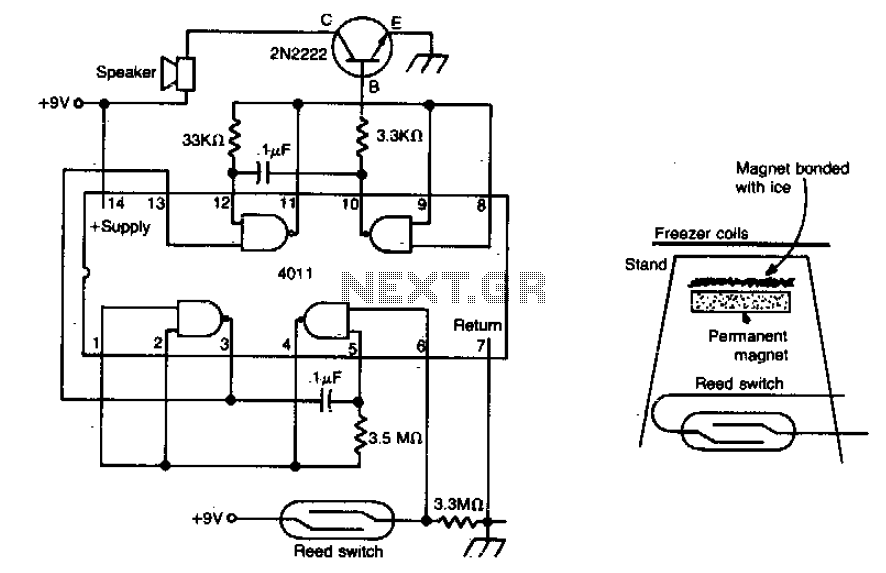
The meltdown consists of a magnet secured to a small stand by ice. A reed switch is positioned beneath the magnet. When the ice melts, the magnet drops onto the switch, closing it and completing the alarm circuit. The described...