
Water Alarm Circuit
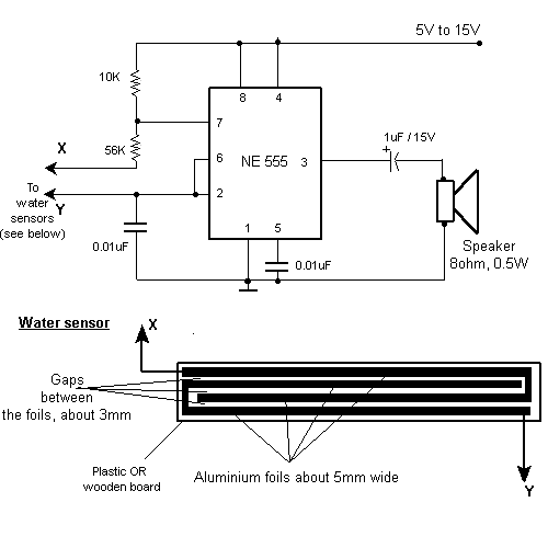
The circuit consists of a 555 timer configured in astable mode, which continuously oscillates to produce a square wave output. The frequency of this output can be adjusted by selecting appropriate resistor and capacitor values connected to the 555 timer. In this application, the output frequency is set to around 1 kHz, which corresponds to a tone that can be easily recognized as an alarm sound.
The sensor component, typically a pair of conductive probes, is placed in a position where it can detect the presence of water. When water bridges the gap between the probes, it completes the circuit, triggering the 555 timer. The output of the timer is connected to a speaker or buzzer, which emits the audible alarm.
To ensure reliable operation, it is crucial to select the right resistors and capacitors for the desired frequency and to consider the sensitivity of the sensor. Additionally, incorporating a diode may be beneficial to protect the circuit from potential back EMF generated by the buzzer.
Power supply considerations should also be addressed, as the circuit typically operates on a low voltage, often supplied by batteries or a DC power source. Proper grounding and layout design will enhance the circuit's performance and longevity. Overall, this water detection alarm circuit provides an effective solution for alerting users to the presence of water through a simple yet efficient electronic design.This circuit gives out an alarm when its sensor is wetted by water. A 555 astable multivibrator is used here which gives a tone of about 1kHz upon detecting water. .. 🔗 External reference
Related Circuits

This type of charger transfers RF energy from an inductor (L2) to an external pickup coil. The pickup coil is connected to a rectifier and a battery that requires charging. This design is advantageous as it eliminates the need...

This is a simple circuit utilizing the NE555 integrated circuit (IC) designed to generate metronomes. Such a circuit is particularly beneficial for music learners. The configuration operates as an astable multivibrator centered around the NE555. The output frequency is...
The SFH505A, manufactured by Siemens, integrates an infrared diode receiver, amplifier, demodulator, and a band-pass filter to minimize interferences. This circuit operates effectively in various applications. The SFH505A is a versatile optical receiver module designed for infrared communication systems. It...
The integrated circuit LA3607 enables the configuration of a 7-band graphic equalizer for a single audio channel by incorporating additional capacitors and variable resistors. The cutoff frequency can be modified using variable resistors. It demonstrates high stability when handling...
This circuit utilizes two operational amplifiers configured as triangular wave oscillators. It demonstrates a practical application of a relaxation oscillator that employs a voltage comparator to execute the switching function. The schematic in FIG. 2 illustrates the composition of...
Quasi square wave resonant converters, also referred to as quasi resonant (QR) converters, facilitate the design of flyback Switch Mode Power Supplies (SMPS) with diminished Electro Magnetic Interference (EMI) and enhanced efficiency. Due to their low noise generation, QR...