
Esquire Wiring

To create a comprehensive electronic schematic description, it is essential to focus on the wiring layout, components involved, and potential troubleshooting approaches. A typical wiring schematic includes a clear representation of the circuit elements, such as resistors, capacitors, diodes, and integrated circuits, along with their connections.
In this scenario, the wiring is suspected to have issues stemming from human error. This could involve incorrect connections, misplaced components, or inadequate soldering techniques. A methodical approach to troubleshooting is recommended. This includes visually inspecting the circuit for any loose connections or shorts, using a multimeter to verify continuity and resistance values, and ensuring that all components are correctly oriented and rated for the intended application.
Additionally, documenting the circuit with clear labels and annotations can aid in identifying potential problem areas. Utilizing software tools for schematic design can enhance clarity and ensure that the wiring conforms to standard practices. By providing detailed images and descriptions of each section of the circuit, it becomes easier to pinpoint and rectify any wiring mistakes, ultimately enhancing the reliability and functionality of the electronic system.and the most likely problem with my wiring is ME. My apologies for the long post but I thought the more information and pictures I can provide the.. 🔗 External reference
Related Circuits
The following circuit illustrates an Electric Car Audio Project. Features include a Rockford Fosgate Punch 4080DSM amplifier, which operates in a bridged 2-channel configuration at 4 ohms for component speakers. The Electric Car Audio Project utilizes the Rockford Fosgate Punch...
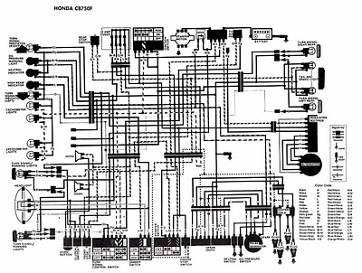
The following image illustrates the electrical wiring connection diagram for the Honda Motorcycle CB750F. It details the connections between various Honda components, including the right turn signal indicator light, oil pressure warning light, neutral indicator, high beam indicator, turn...
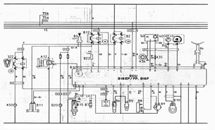
The following document contains information related to the electrical installation schematic diagram for the Volvo 440. It includes the wiring schematic for the Volvo 440, 460, and 480 series. The Volvo 440, 460, and 480 series vehicles feature a comprehensive...
1990 Toyota Corolla Brake Light Wiring Diagram. The 1990 Toyota Corolla brake light wiring diagram provides a detailed overview of the electrical connections and components involved in the brake light system of the vehicle. The diagram illustrates the relationship between...
A 1989 S10 with a 4.3L engine and automatic transmission is being reassembled after the engine was removed. The main issue encountered is related to the starter wiring. The solenoid has one large terminal connected to the positive side...
1988 Honda Civic Tail Light Wiring Diagram. The 1988 Honda Civic tail light wiring diagram provides a detailed representation of the electrical connections and components associated with the tail light system of the vehicle. This schematic typically includes information on...