
1988 Honda Civic Tail Light Wiring Diagram
No description available.
Related Circuits
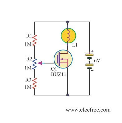
Changing the value of R2 alters the intensity of the lamp in this circuit, demonstrating the utility of a MOSFET as a variable resistor. An N-Channel Power MOSFET, designated as Q1, is utilized in the circuit. The specific part...
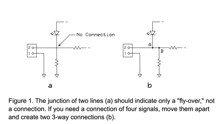
This section provides guidance on avoiding common issues with charts, diagrams, and other graphic representations. Engineers frequently utilize diagrams; however, while a detailed schematic diagram on a lab bench may accurately depict the work, it could present excessive information...
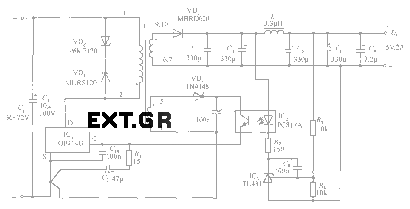
The circuit diagram includes an input filter capacitor C1 and a primary clamp composed of VDz and VD1. The resistor R1 is connected to the control terminal. C2 serves as a bypass capacitor. The TOP414GC-S is connected in parallel...
The following circuit illustrates the CD4017 integrated circuit (IC) used in an automatic room lights sensor circuit diagram. Features include a single light sensor utilizing two light-dependent resistors (LDRs). The CD4017 is a decade counter IC that can drive multiple...
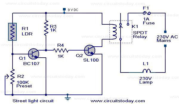
A street light that automatically switches ON when night falls and turns OFF when the sun rises. The circuit uses an LDR to sense the light. The automatic street light circuit functions by utilizing a Light Dependent Resistor (LDR) as...
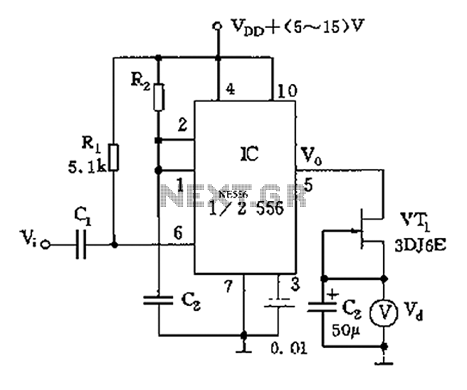
The circuit utilizes switch contacts that are proportional to the speed pulse signal Vi. A differential signal is fed into the trigger side of an integrated circuit (IC), specifically a 555 timer configured in monostable mode (1/2 556), to...